
EMC metal-plate antenna and a communication system using the same

a metal-plate antenna and communication system technology, applied in the direction of antennas, antenna details, antenna earthings, etc., can solve the problems of reducing the usable space inside the wireless communication apparatus, reducing the performance of the antenna, and increasing the difficulty of design, so as to reduce electromagnetic coupling effect, improve the receiving and transmitting quality of wireless signals, and avoid the effect of the antenna

Active Publication Date: 2008-12-30
IND TECH RES INST +1
View PDF14 Cites 14 Cited by
  • Summary
  • Abstract
  • Description
  • Claims
  • Application Information

AI Technical Summary

Benefits of technology

[0012]An aspect of the present invention is to provide a built-in antenna, to which spacing from other major components is not needed while the antenna still possesses the electromagnetic compatible behavior to effectively decrease the influence on the antenna from other electronic components near to the antenna. Thus, the inside usable capacity of a wireless communication system is increased and the size of the wireless communication apparatus can be further compact.
[0013]Another aspect of the present invention is to provide a built-in antenna of unified design by metal processing to reduce fabrication cost.
[0014]Another aspect of the present invention is to provide an EMC (electromagnetic compatible) built-in antenna, capable of increasing the compatibility between the antenna and other components and adaptation in a wireless communication apparatus. In other words, the flexibility to dispose an antenna inside a wireless communication apparatus is increased.
[0017]Another embodiment of the present invention provides a wireless communication apparatus, which includes: an internal component; and an EMC built-in antenna. The EMC built-in antenna has an antenna shielding metal wall, capable of effectively reducing electromagnetic coupling between the antenna and the internal components and avoiding the antenna from the signal influence of the internal components. There is no spacing required between the antenna and the internal components.
[0018]Another embodiment of the present invention provides a method for improving the receiving and transmitting quality of wireless signals in a wireless communication apparatus. The wireless communication apparatus includes a built-in antenna and a signal source. The method includes: providing the wireless communication apparatus with a common ground plane; providing the built-in antenna with an electromagnetic shielding metal wall electrically connected to the common ground plane. The electromagnetic shielding metal effectively encircles the built-in antenna and is capable of effectively protecting the built-in antenna from electromagnetic coupling of the signal source such to improve the receiving and transmitting operations of the wireless signals of the built-in antenna. There is no preserved spacing needed between the built-in antenna and the signal source. Even if other signal sources are added in the wireless communication apparatus, the whole behavior of the built-in antenna almost does not change.

Problems solved by technology

Therefore, if the spacing between the antenna and other components is not large enough, a negative electromagnetic coupling occurs, which leads to the degradation in the antenna performance.
Hence, to apply an antenna in a wireless communication apparatus, the EMC influence of the surroundings must be considered, which increases the difficulty of design.
However, the isolation spacing preservation reduces usable spaces inside the wireless communication apparatus, and also limits a wireless communication apparatus to be light and compact.
Besides, since the electromagnetic coupling between the antenna and other components would be varied by the position change of other components, large effects on the antenna performance are expected.
As a matter of fact, the above-mentioned antenna designs did not consider the shielding of an antenna itself yet.
Therefore, when such kind of antennas is disposed near other electronic components, an extra spacing is required for reducing the electromagnetic coupling between the antenna and other electronic components, which results in an inefficient usage of the limited available space.
If the spacing preserved is not sufficient, a frequency shift and an impedance change occur, which affect the signal quality and largely reduce the antenna performance due to the electromagnetic coupling.
However, the conventional antenna does not have its own shielding.
When the distance between the antenna and the shielded components is too small, the antenna performance would be degraded due to a strong electromagnetic coupling.
To reduce the coupling, an extra spacing between the conventional antenna and the components is required, which leads to an inefficient usage of the avaiable space inside the mobile communication apparatus.
Besides, when the position relation changes between the antenna and other components, the antenna performances would be varied, and the antenna needs to redesigned, leading to a labor waste.

Method used


Image

  • EMC metal-plate antenna and a communication system using the same
  • EMC metal-plate antenna and a communication system using the same
  • EMC metal-plate antenna and a communication system using the same

Examples


first embodiment

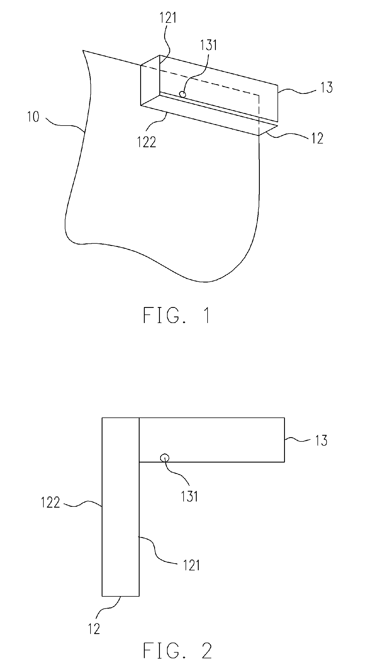
[0030]Referring to FIGS. 1 and 2 for showing an antenna according to the present invention. The antenna mainly includes a ground plane 10, a bent ground plate 12 and a radiating plate 13. The ground plane 10 is for signal ground of the entire antenna and the communication system using the antenna.

[0031]The bent ground plate 12 is perpendicular to the ground plane 10 and used as an electromagnetic shielding metal wall of the antenna for providing the antenna with a required shielding effect to effectively decrease the influence on the antenna from other electronic components (or signal sources) surrounding the antenna. The bent ground plate 12 is formed of a rectangle-like metal plate or a plate plated by metal or the equivalent. The bent ground plate 12 is formed by bending the rectangle-like metal plate or the plated plate at least once. In addition, the shape thereof after the bending is roughly of an L shape. The bent ground plate 12 has a first edge 121 and a second edge 122. Th...

second embodiment

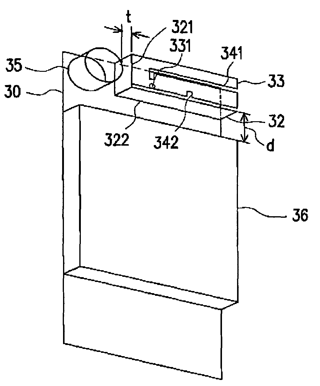
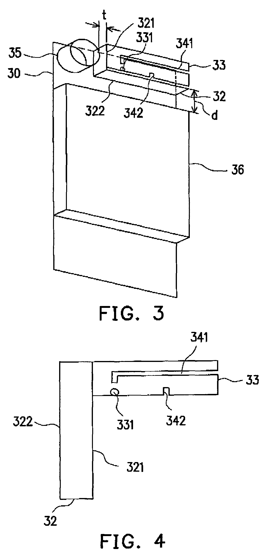
[0035]The antenna architecture of the second embodiment mainly includes a ground plane 30, a bent ground plate 32 and a radiating plate 33. The bent ground plate 32 is perpendicular to the ground plane 30 and is formed of a rectangle metal plate or a plate plated with metal or the equivalent. The bent ground plate 32 is formed by bending the metal plate or the plated plate at least once. In addition, the shape thereof after the bending is roughly of an L shape. The bent ground plate 32 has a first edge 321 and a second edge 322. The second edge 322 is electrically connected to the grounded plane 30. The radiating plate 33 is for generating operating resonant modes of the antenna. The radiating plate 33 has a signal feeding point 331 and two gaps 341 and 342, and is roughly parallel to the ground plane 30. The radiating plate 33 is electrically connected to the first edge 321 of the bent ground plate and encircled by the bent ground plate 32. The gap 341 makes two resonant paths in t...


PUM


Abstract

An EMC (electromagnetic compatible) antenna having a shielding metal wall to effectively reduce the possible coupling with nearby electronic elements is presented. The antenna includes: a ground plane, a bent ground plate, and a radiating plate. The bent ground plate is vertically connected to the ground plane and functions as an effective shielding metal wall to eliminate or greatly reduce the possible EM coupling between the antenna and nearby electronic elements. The radiating plate is used to generate the operating resonant mode of the antenna and is generally parallel to the ground plane. The radiating plate is also electrically connected to and encircled by the bent ground plane.

Description

CROSS-REFERENCE TO RELATED APPLICATION[0001]This application claims the priority benefit of Taiwan application serial no. 94140042, filed on Nov. 15, 2005. All disclosure of the Taiwan application is incorporated herein by reference.BACKGROUND OF THE INVENTION[0002]1. Field of Invention[0003]The present invention relates to an EMC (electromagnetic compatible) metal-plate antenna and a communication system using the same, and particularly to a built-in EMC antenna and a communication system using the same, which is capable of effectively reducing possible electromagnetic coupling between the antenna and other electronic elements without an isolation spacing.[0004]2. Description of Related Art[0005]Along with the thriving development of wireless communications, various communication products and communication technologies are being emerged in flourish, and the wireless communication products have gradually become an indispensable part in people's living. With drastic competitions in t...

Claims


Application Information

Patent Timeline
Patent Type & Authority Patents(United States)
IPC IPC(8): H01Q1/24
CPCH01Q1/243H01Q9/0421
Inventor TANG, CHIA-LUNWONG, KIN-LUSU, CHIH-MING
Owner IND TECH RES INST
Learn More