Computer system, method and system for controlling light

a computer system and light control technology, applied in the field of methods for controlling lights, can solve the problems of inconvenient sound playback in a quiet environment, error cannot be displayed in the display, and user inconvenience, so as to achieve the effect of not increasing the hardware cost of the computer system

Active Publication Date: 2013-03-19
ASUSTEK COMPUTER INC
View PDF18 Cites 4 Cited by
  • Summary
  • Abstract
  • Description
  • Claims
  • Application Information

AI Technical Summary

Benefits of technology

[0008]Accordingly, the present invention is directed to a method for controlling a light, wherein the current status of a computer system is displayed by using an original light of the computer system so that the hardware cost of the computer system is not increased.
[0019]In the present invention, the original service of a light can be interrupted and the operation of the light can then be controlled according to the current status of the computer system. Thereby, the current status of the computer system can be clearly and quickly displayed to a user without increasing the hardware cost of the computer system.

Problems solved by technology

Generally speaking, if an error is detected during the POST (for example, no memory is found or the memory is faulty), the error cannot be displayed in the display.
For example, it is very inconvenient to play a sound in a quiet environment (for example, in an office).
Even in a general environment, it is not a comfortable way to notify a user of a hardware error.
Besides, the capability of human's audition to identify the length of a sound is not very reliable.
Moreover, in the conventional technique, only one sound is played through the speaker when an error is detected during a POST, and if the user does not catch the sound clearly, the user cannot determine the error correctly.

Method used


Image

  • Computer system, method and system for controlling light
  • Computer system, method and system for controlling light
  • Computer system, method and system for controlling light

Examples


Embodiment Construction

[0028]Reference will now be made in detail to the present preferred embodiments of the invention, examples of which are illustrated in the accompanying drawings. Wherever possible, the same reference numbers are used in the drawings and the description to refer to the same or like parts.

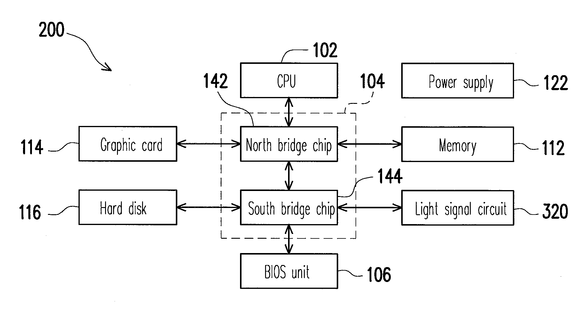
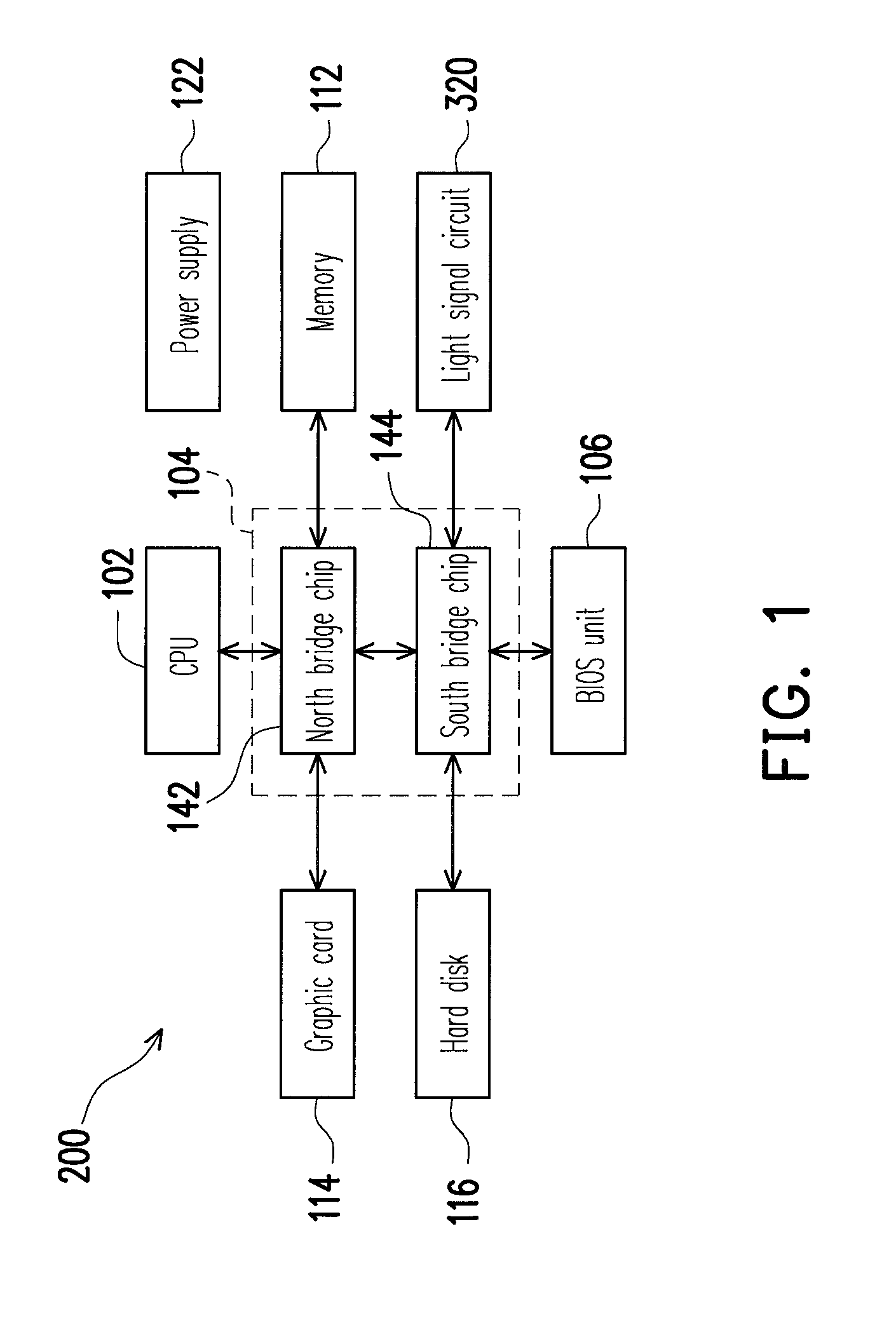
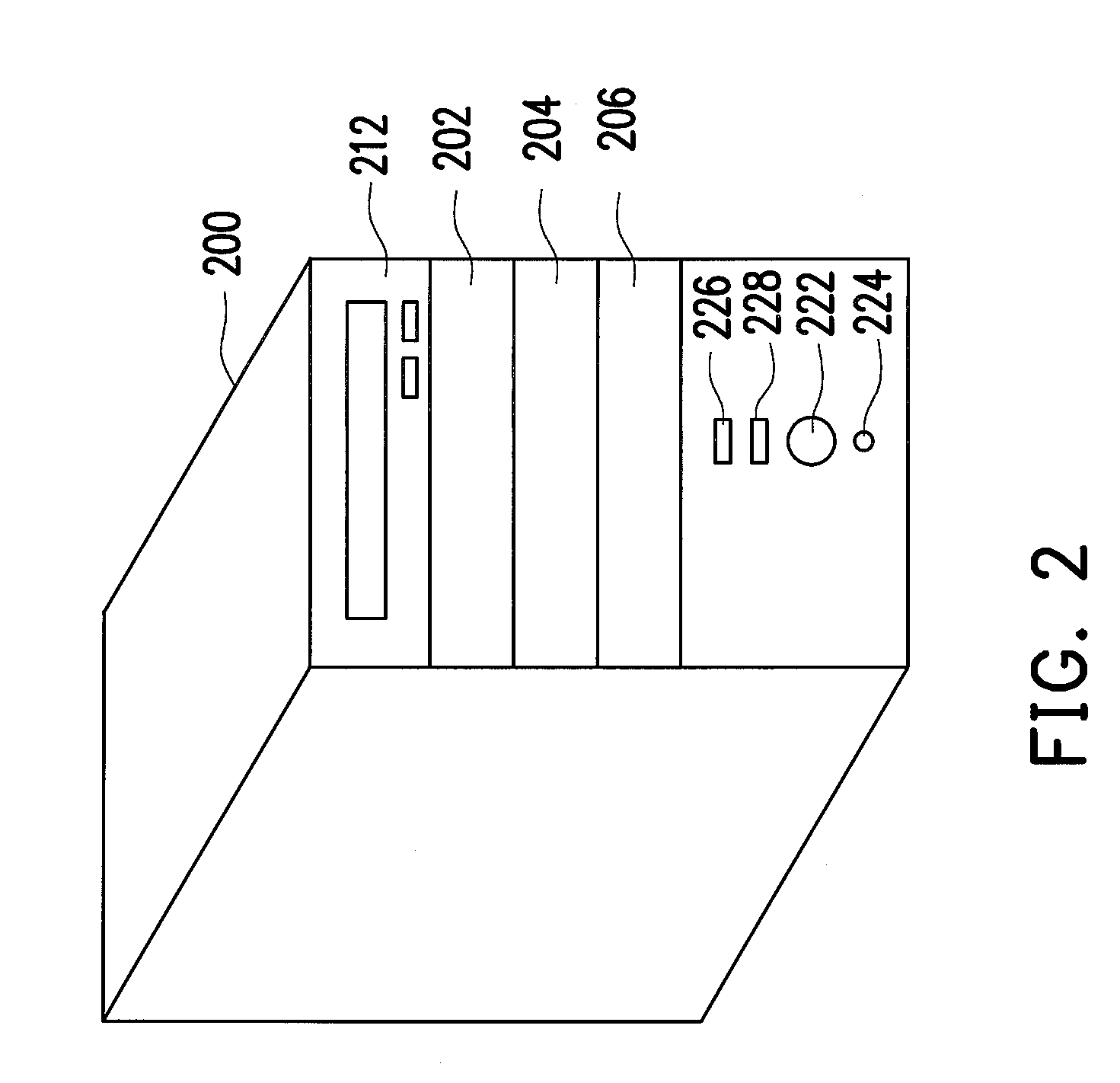
[0029]FIG. 1 is a block diagram of a computer system according to an embodiment of the present invention. FIG. 2 illustrates the appearance of a computer system according to an embodiment of the present invention. Referring to FIG. 1 and FIG. 2, the computer system 200 in the present embodiment may be a desktop computer; however, the present invention is not limited thereto. A plurality of slots 202, 204, and 206 are disposed on the computer system 200, and some electronic devices (for example, a CD-ROM 212) are installed on the computer system 200 through these slots. Besides, a plurality of function buttons, such as the buttons 222 and 224, are further disposed on the case of the computer system 20...


PUM


Abstract

A method for controlling a light is provided. The method is suitable for a computer system. The method includes interrupting an original service of the light and obtaining the authority to control the light. The method also includes controlling the operation of the light according to a current status of the computer system.

Description

CROSS-REFERENCE TO RELATED APPLICATION[0001]This application claims the priority benefit of Taiwan application serial no. 97131232, filed on Aug. 15, 2008. The entirety of the above-mentioned patent application is hereby incorporated by reference herein and made a part of specification.BACKGROUND OF THE INVENTION[0002]1. Field of the Invention[0003]The present invention generally relates to a method for controlling a light, and more particularly, to a method for controlling a light which indicates the current status of a computer system.[0004]2. Description of Related Art[0005]A computer system includes a central processing unit (CPU), a chipset, and a basic input / output system (BIOS) unit. The CPU is coupled to the BIOS unit and other hardware devices (for example, a memory, a graphic card, and a hard disk, etc) through the chipset. Besides, the computer system further includes a power supply which supplies an operating power to the computer system.[0006]The power supply starts to ...

Claims


Application Information

Patent Timeline
Patent Type & Authority Patents(United States)
IPC IPC(8): G08B21/00
CPCG06F11/326
Inventor HUANG, PAI-CHINGKAO, CHAN-HSUAN
Owner ASUSTEK COMPUTER INC
Why Eureka
Try Eureka