Variable compression ratio device for internal combustion engine

a compression ratio and internal combustion engine technology, applied in the direction of engine controllers, machines/engines, mechanical devices, etc., can solve the problems of reducing reduce the bending stress reduce the rigidity of the actuator rod, and increase the bending stress in the interior of the actuator rod

Active Publication Date: 2013-03-19
NISSAN MOTOR CO LTD
View PDF41 Cites 11 Cited by
  • Summary
  • Abstract
  • Description
  • Claims
  • Application Information

AI Technical Summary

Benefits of technology

[0006]However, forming such a deep fork in the tip end of the actuator rod causes the rigidity of the actuator rod to decrease. For example, when a rotation angle of the control shaft increases such that a component force in a transverse direction of the actuator rod, of a load acting on the actuator rod, becomes larger than a component force in an axial direction of the actuator rod, bending stress in the interior of the actuator rod increases. As a result, it may become necessary to suppress the engine output in order to reduce the bending stress of the actuator rod to an allowable stress range.
[0007]It is therefore an object of this invention to reduce a bending load acting on an actuator rod of a variable compression ratio device and improve the controllability of the compression ratio.

Problems solved by technology

However, forming such a deep fork in the tip end of the actuator rod causes the rigidity of the actuator rod to decrease.

Method used


Image

  • Variable compression ratio device for internal combustion engine
  • Variable compression ratio device for internal combustion engine
  • Variable compression ratio device for internal combustion engine

Examples


first embodiment

[0083]Similarly to the first embodiment, a variable compression ratio device according to this embodiment is constituted such that the movement amount of the actuator rod 13 per rotation angle of the control shaft 7 is larger at a high compression ratio than a low compression ratio.

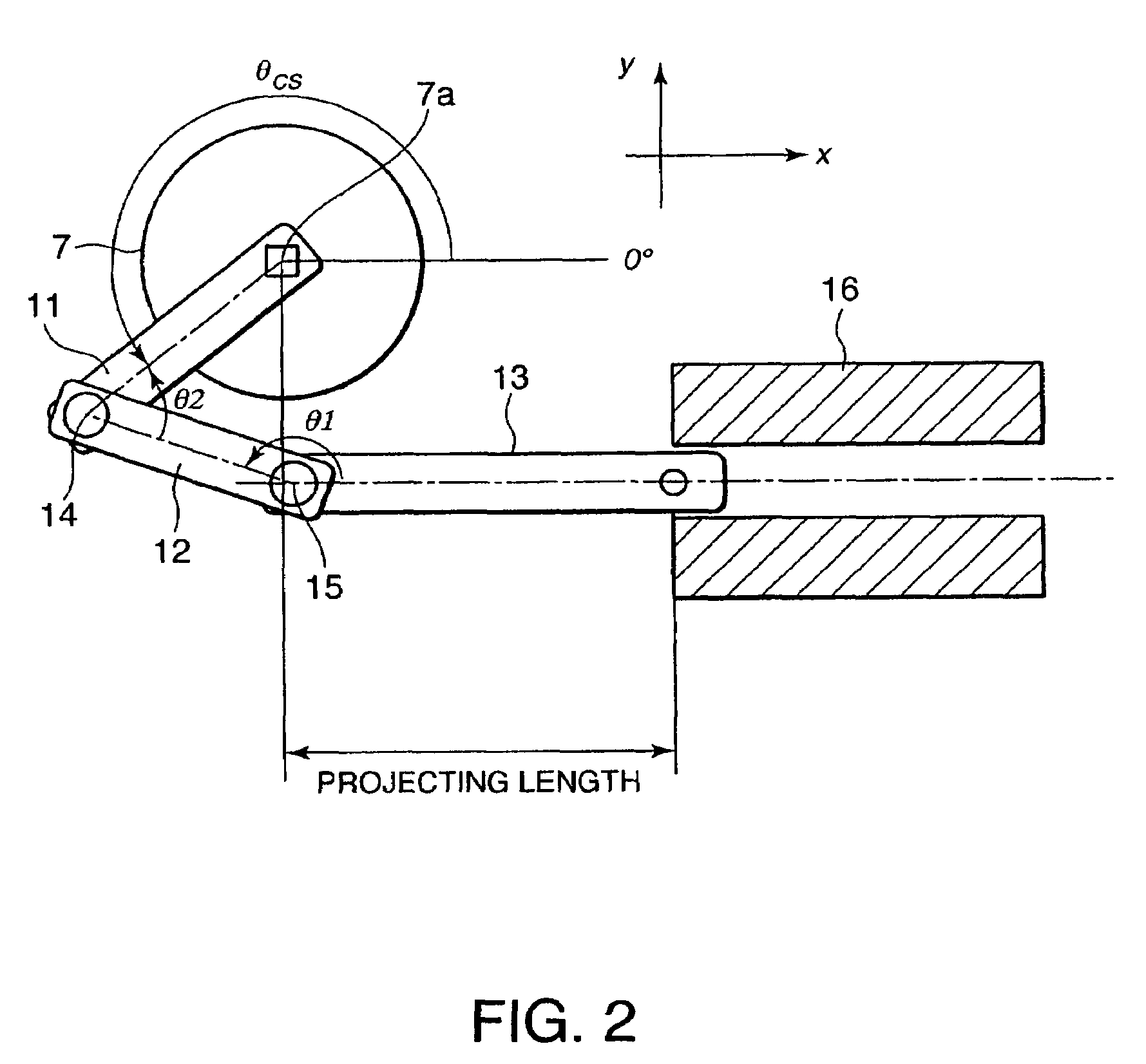
[0084]As shown in FIG. 12, the rotation angle θcs of the control shaft 7 is set to be close to 180 degrees at the minimum compression ratio and to be close to 270 degrees at the maximum compression ratio.

[0085]By means of this setting, the compression ratio increases as the rotation angle θcs of the control shaft 7 increases. However, in contrast to the first embodiment, the increase rate of the compression ratio per unit rotation angle decreases as the rotation angle θcs of the control shaft 7 increases as shown in FIG. 13. In other words, variation in the compression ratio relative to variation in the rotation angle θcs of the control shaft 7 decreases as the compression ratio approaches the maximum com...

third embodiment

[0086]Referring to FIGS. 14A and 14B, FIGS. 15-17, FIGS. 22A and 22B, FIGS. 23A-23G, and FIGS. 24A-24G, this invention will be described.

[0087]FIG. 14A shows the state of the variable compression ratio device in the vicinity of the minimum compression ratio. FIG. 14B shows the state of the variable compression ratio device in the vicinity of the maximum compression ratio.

[0088]In this embodiment, similarly to the first embodiment, the rotation angle θcs of the control shaft 7 at the minimum compression ratio is close to 90 degrees, and the rotation angle θcs of the control shaft 7 at the maximum compression ratio is close to 180 degrees. Accordingly, the effective arm length by which a load F3 acting on the control shaft 7 is converted into the control shaft torque Tcs reaches a maximum at the maximum compression ratio.

[0089]Further, the fixing lever 11, connecting link 12, and actuator rod 13 are disposed such that the angle θ2 formed by the connecting link 12 and the actuator rod ...

fourth embodiment

[0118]Referring to FIGS. 18-21, this invention will be described.

[0119]A variable compression ratio device according to this embodiment differs from the first embodiment in the displacement region of the offset pin 10, the connecting pin 14, and the connecting pin 15.

[0120]Referring to FIG. 18, in the variable compression ratio device according to this embodiment, the offset pin 10 displaces over the second quadrant and third quadrant so as to be positioned in the second quadrant at the minimum compression ratio and in the third quadrant at the maximum compression ratio.

[0121]The connecting pin 14 displaces over the third quadrant and fourth quadrant so as to be positioned in the third quadrant at the minimum compression ratio and in the fourth quadrant at the maximum compression ratio. Furthermore, the connecting pin 14 is positioned above the axis of the actuator rod 13 throughout the entire displacement region, and comes closest to the axis of the actuator rod 13 at the intermedi...


PUM


Abstract

A variable compression ratio device for an internal combustion engine comprises a control shaft (7) that varies a compression ratio of the internal combustion engine in accordance with a rotational displacement, and a linear actuator (13, 16, 17, 18). A connecting link (12) connects a first point (14) offset from a rotation axis (7a) of the control shaft (7) to an actuator rod (13) of the linear actuator (13, 16, 17, 18). Thus, a bending load acting on the actuator rod (13) is reduced, and controllability of the compression ratio is improved.

Description

FIELD OF THE INVENTION[0001]This invention relates to a variable compression ratio device which varies a compression ratio of an internal combustion engine via a plurality of links.BACKGROUND OF THE INVENTION[0002]JP2002-115571A, published by the Japan Patent Office in 2002, discloses a variable compression ratio device that connects a piston and a crankshaft of an internal combustion engine via a plurality of links so as to vary the compression ratio of the internal combustion engine. In this prior art device, the piston and the crankshaft are connected via an upper link and a lower link, and by varying the tilt of the lower link, the compression ratio is varied. The tilt of the lower link is varied using the following mechanism.[0003]One end of a control link is connected to the lower link, and another end of the control link is connected to a control shaft, which is substantially parallel to the crankshaft, in an eccentric position. With this constitution, when the control shaft ...

Claims


Application Information

Patent Timeline
Patent Type & Authority Patents(United States)
IPC IPC(8): F02B75/04
CPCF02B75/048
Inventor HIYOSHI, RYOSUKETANAKA, YOSHIAKITAKEMURA, SHINICHI
Owner NISSAN MOTOR CO LTD
Why Eureka
Try Eureka