Brake with field responsive material

a technology of field responsive materials and brakes, which is applied in the direction of shock absorbers, mechanical equipment, transportation and packaging, etc., can solve the problems of limited space allotted for the use of these devices, and achieve the effect of restricting relative rotation

Active Publication Date: 2013-03-19
LORD CORP
View PDF89 Cites 20 Cited by
  • Summary
  • Abstract
  • Description
  • Claims
  • Application Information

AI Technical Summary

Benefits of technology

[0013]In another aspect of the invention, a controllable MR brake includes a rotor comprising first and second rotor surfaces, an outer periphery, and a working portion on at least one of the first and second rotor surfaces at a position proximate to the outer periphery. The rotor is fixed to a shaft at one shaft end and the rotor and the shaft are rotatable together. A housing includes a first chamber rotatably housing the rotor therein, and including a magnetic field generator spaced from the rotor and configured and positioned for conveying a magnetic flux acting on a volume of controllable material located in the first housing chamber in contact with at least one surface proximate the outer periphery. The controllable material is contained within the first chamber to be in contact with at least the working portion of the rotor. Electronics serve to control and monitor operation of the brake. In a more specific aspect, a second chamber is included in the housing and houses the electronics therein to provide a compact and integrated MR brake with electronics housed therein.
[0017]Yet still further, the connection between the shaft and the rotor may be arranged so as to allow some backlash between the rotor and the shaft, and the control electronics can be arranged for detecting movement of the shaft and for causing the magnetic field generator to reduce magnetic field in response to the shaft movement to allow easy movement of the control device connected to the brake, such as a steering wheel, back from an end-of-movement position.
[0020]In such a configuration, the walls of the chamber in which the rotor is housed can be tapered. The taper can be an amount sufficient to enhance migration of field controllable material away from the shaft and toward the working surface of the rotor. In addition, other alternative structures can be built into the rotor proximate the shaft, the housing, and / or on the shaft itself as to create a tortuous path for the field controllable material, making it difficult to have it migrate towards the shaft and in the direction of seals associated with the shaft to retain the material within the chamber housing the rotor. The seals used can be conventional seals and / or of other configurations as will be readily apparent to those of ordinary skill in the art, such as “v-seals” of conventional construction. Similarly, conventional bearings, such as roller elements or bearings, can be used in supporting the shafts as well as other types of bearings which are well known to those of ordinary skill in the art, interchangeable therewith, including, without limitation, dry shaft bearings and the like.

Problems solved by technology

Often, the space allotted for the use of these devices is limited and specific applications require that the devices be maintained as small as possible, while still providing sufficient resistance to the control device.

Method used


Image

  • Brake with field responsive material
  • Brake with field responsive material
  • Brake with field responsive material

Examples


first embodiment

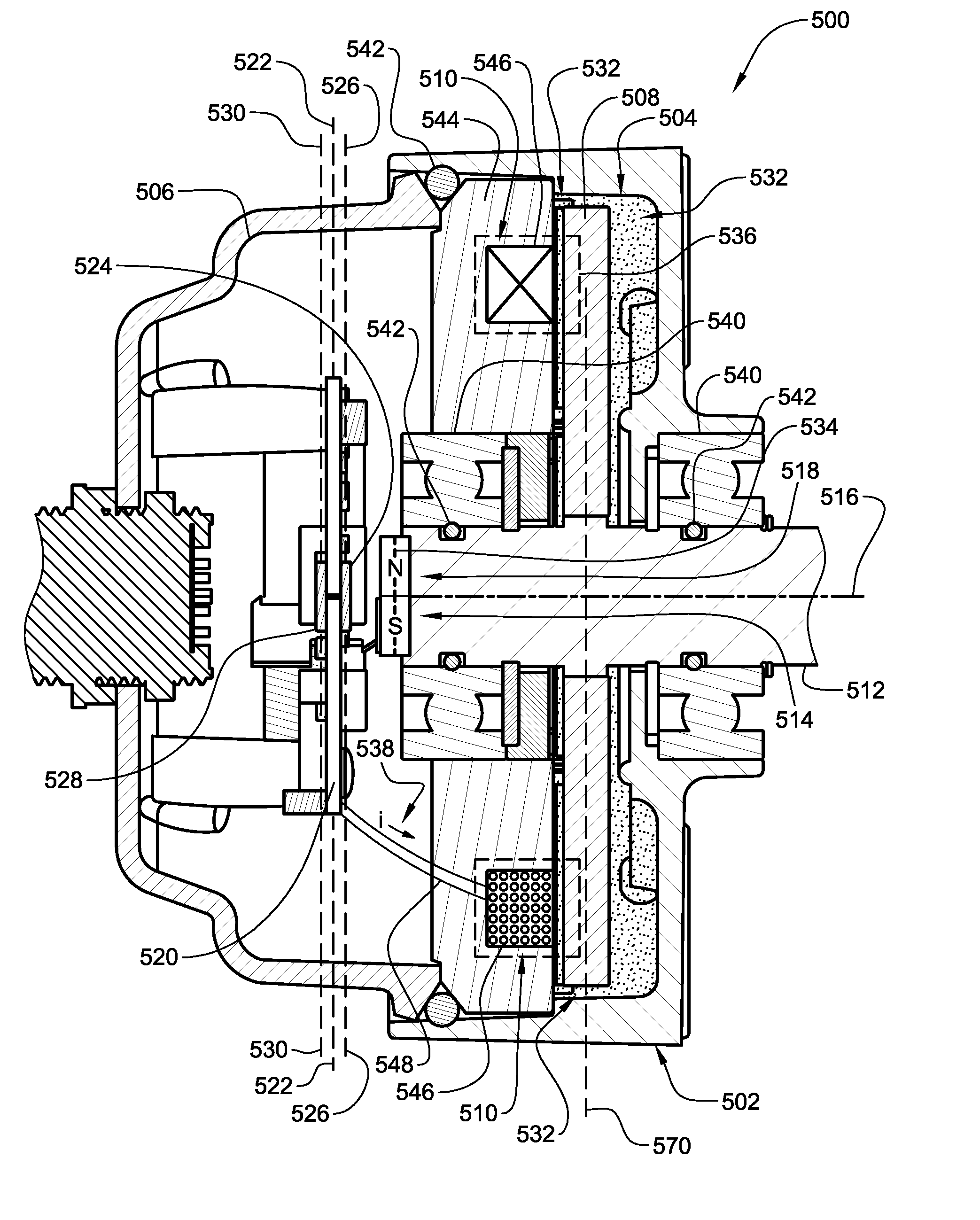
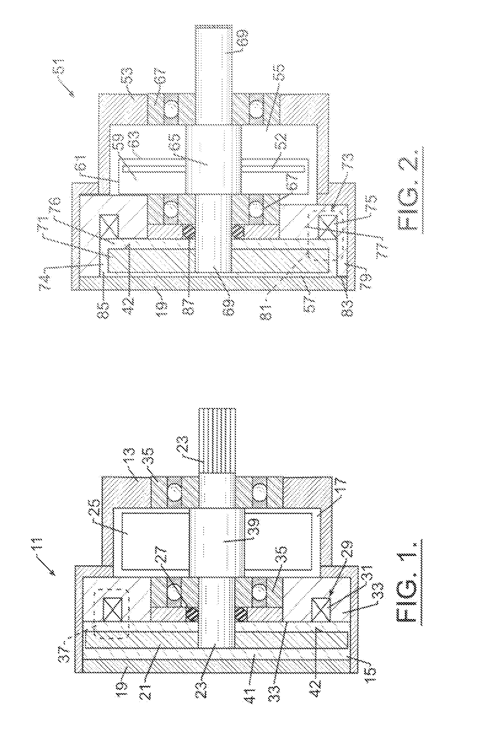
[0046]For purposes of describing the invention, rotor 21 is disk-shaped and is supported on a shaft 23 within the housing 13 for rotation within the housing chamber 15. The rotor includes first and second surfaces and an outer periphery. The surfaces include working portions near the outer periphery at regions on the surface of the rotor upon which the magnetic field acts. The working surface is identified at 42 in FIG. 1. A typical magnetic flux line 37 associated with the applied magnetic field is shown dashed in FIG. 1.

[0047]Brake housing 13 includes an open end where the first chamber 15 is located and the open housing end and the chamber is closed and sealed by closing plate 19. The first chamber also contains therein a volume of field controllable material 41 and electromagnetic field generators 29. The field generators comprise, for example, in one configuration, coil 31 and pole piece 33. When activated, the magnetic field generator 29 creates magnetic flux 37. In FIG. 1 the...

second embodiment

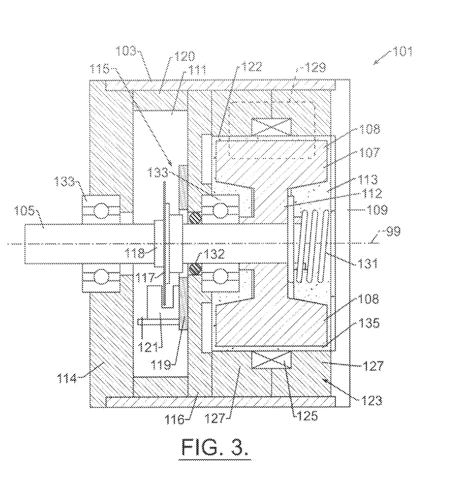
[0058]In the embodiment of FIG. 3, the seal 132 required to prevent migration of material 135 from the first chamber 113 to the second chamber 111 is shown seated in bearing support plate 116. Such a suitable seal may comprise the seal disclosed in the description of first and second embodiment brakes. The suitable conventional seal may be supported in the bearing support plate 116 or within bearings 133. An annular shroud 120 is located between plates 114 and 116. Shroud 120, in combination with plates 114 and 116 encloses the sensing means 115 within chamber 111.

[0059]Returning again to the rotor 107 of the third embodiment brake 101, rotor 107 is not substantially disk-shaped like disks 21 and 71 previously described. As shown in FIG. 3, rotor enlarged peripheral portion 108 is located proximate electromagnetic coil 125 of field generator generally identified at 123. As shown by the stippling representing field responsive material 135, an annular gap 122 separates the portion 108...

third embodiment

[0061]The third embodiment brake 101 comprises a return-to-center acting device, such as a torsion or torsional center-return spring 131 which is mounted within first housing chamber 113. Other center return devices may comprise bungee cords or other type elastic components. Generally the suitable center return device is any device that stores energy as the rotor and / or shaft are / is displaced from a center or start position or orientation and then at a particular displacement releases the stored energy to return the rotor and shaft to the start orientation. The particular displacement that results in a release of the stored energy may comprise for example, the operator releasing the shaft or rotor or the shaft or rotor reaching a maximum angular displacement. The torsion return spring 131 typically assumes a torque free condition at the center position of a device with which brake 101 may be associated, such as a steering wheel at the center position of the device. The return to cen...


PUM


Abstract

A controllable brake includes a housing and a rotor supported on a shaft. The rotor is housed within a chamber containing a field controllable material which is acted upon by a magnetic field generator to impede movement of the rotor. The shaft is supported by bearings. The controllable brake housing defines a second housing chamber adapted to enclose means for monitoring and / or controlling the brake and in this way, an integrated, compact controllable brake is provided.

Description

CROSS REFERENCE[0001]This application is a Continuation In Part (CIP) of U.S. patent application Ser. No. 11 / 042,277 filed Jan. 25, 2005 now U.S. Pat. No. 7,198,140, which is a Divisional of U.S. patent application Ser. No. 10 / 037,118 filed on Oct. 25, 2001, now U.S. Pat. No. 6,854,573, all of which this application claims the benefit of, and incorporates by reference.FIELD OF THE INVENTION[0002]The invention relates to the area of brakes, clutches, resistance generating devices and motion control devices. Specifically the invention relates to devices employing a field responsive material for controlling torque in rotary acting devices or linearly-acting devices.BACKGROUND OF THE INVENTION[0003]Devices employing a field responsive material for damping and controlling vibration and shock are known. Such a field responsive material may comprise a suitable magnetorheological (MR) material well known to one skilled in the art. As the description proceeds, the field responsive material m...

Claims


Application Information

Patent Timeline
Patent Type & Authority Patents(United States)
IPC IPC(8): F16F15/03
CPCF16D57/002
Inventor ST. CLAIR, KENNETH A.MARJORAM, ROBERT H.HARDIN, WILLIAM C.HONTZ, MARIANEKOESTER, STEPHEN
Owner LORD CORP
Why Eureka
Try Eureka