System and method for pedestal adjustment

a technology of pedestal and preheat ring, which is applied in the direction of crystal growth process, transportation and packaging, and chemically reactive gases, etc., can solve the problems of unsatisfactory visual measurement, loss of productivity, and non-uniform gap between the pedestal and the preheat ring, so as to minimize any downtime and recovery time

Active Publication Date: 2013-03-19
APPLIED MATERIALS INC
View PDF9 Cites 39 Cited by
  • Summary
  • Abstract
  • Description
  • Claims
  • Application Information

AI Technical Summary

Benefits of technology

[0013]Embodiments of the present invention relate to providing a non-contact and in-situ method to precisely measure the pedestal positioning. This measurement is used as a feedback for either manual adjustment or fully automatic closed-loop servo based adjustment of the tilt and translation mechanism until the pedestal is fully level, centered and adjusted for height. The non-contact method allows the measurement to be done in vacuum thus eliminating the need for the chamber to be open and vented significantly minimizing any down-time and recovery time.
[0025]In yet another embodiment, the lateral adjustment assembly used in the substrate processing system includes three adjustment screws nearly equally spaced around the outer ring. The bellows can maintain a pressure difference between the inside and outside of the substrate processing system while adjusting the adjustment screws.
[0029]In yet another embodiment, the method of adjusting a position of a pedestal further includes adjusting the height of the pedestal to a predetermined level without significantly affecting the tilt.
[0037]In yet another embodiment, the step of positioning the pedestal further includes maintaining the angle between a surface on the pedestal and the processing system reference to be less than or equal to 0.15 degrees, adjusting the horizontal location of the pedestal to be within 0.5 mm of the predetermined location, adjusting the height of the pedestal to be within 0.3 mm of the predetermined location, verifying that the angle between a surface on the pedestal and the processing system reference is less than or equal to 0.15 degrees after the adjustments, and securing the position of the pedestal by locking the pedestal into place.
[0039]In yet another embodiment, a method of processing a substrate in a substrate processing system includes pumping a process chamber with a pedestal inside to a pressure less than 80 torr, measuring the tilt and location of the pedestal relative to a processing system reference, leveling the pedestal in response to the tilt measurement to reduce the tilt of the pedestal relative to the processing system reference, and translating the pedestal to be at a predetermined location in response to the location measurement without significantly affecting the tilt. The processing system reference can be rigidly attached to the substrate processing system.

Problems solved by technology

The tilt has been corrected, but a lateral offset has been introduced resulting in a non-uniform gap between the pedestal and the preheat ring.
The reliance on visual measurement is undesirable as it is subjective, time-consuming and prone to human errors.
It also necessitates opening the chamber upper dome requiring the chamber to be vented to atmosphere which brings with it a loss in productivity due to significant down-time and recovery time.
Another drawback to the prior art technique for correcting tilt and lateral location is that the correction is done prior to pumping down the semiconductor processing apparatus.
Pumping down a semiconductor processing apparatus can cause components to shift, move or even flex.
For example, a pedestal that is aligned when the semiconductor processing apparatus is opened can become misaligned for processing conditions because the semiconductor processing apparatus is closed up and pumped down before processing.
Therefore, prior art techniques for correcting tilt and lateral location have the drawback that although components can be aligned during the alignment process, those components may become misaligned before or during processing of wafers.

Method used


Image

  • System and method for pedestal adjustment
  • System and method for pedestal adjustment
  • System and method for pedestal adjustment

Examples


Embodiment Construction

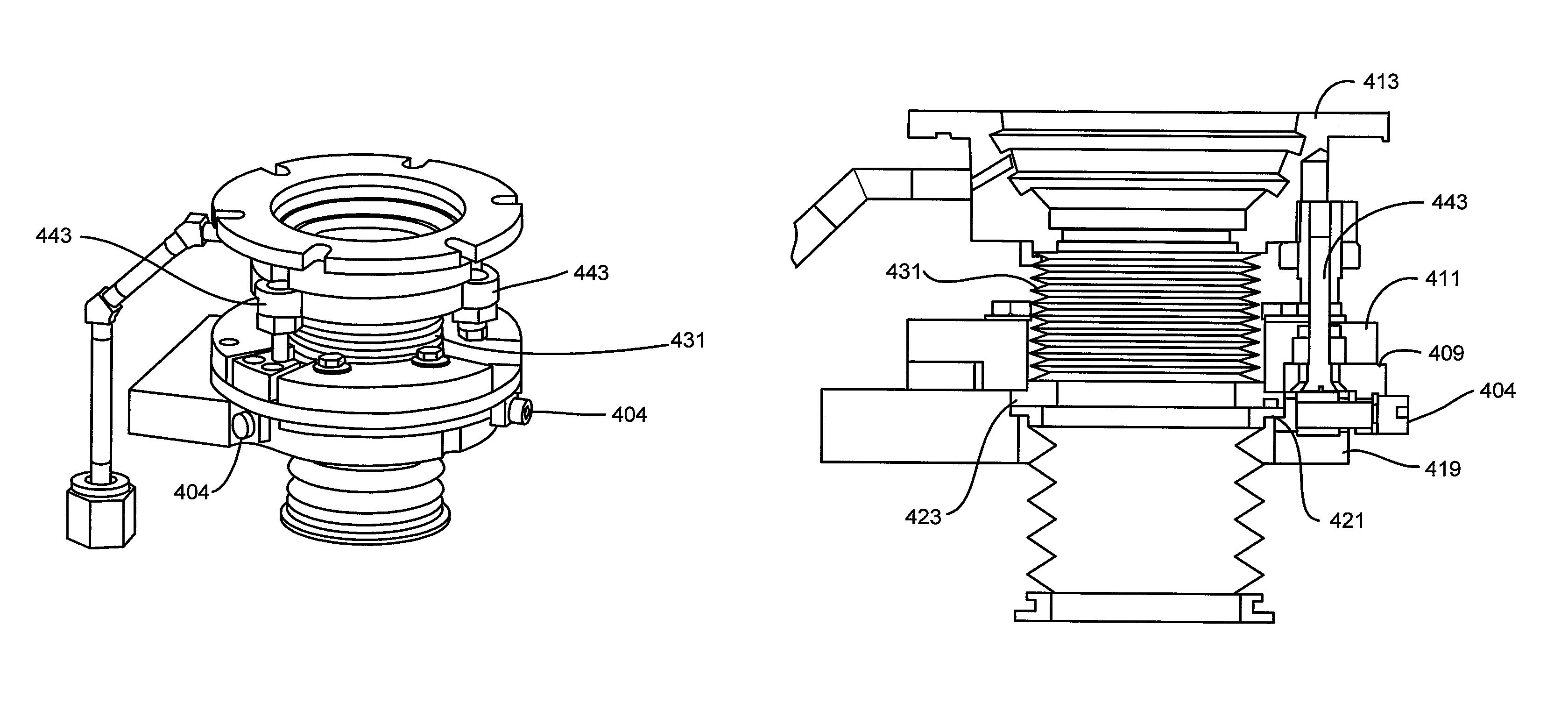
[0056]Aspects of embodiments disclosed herein are used to improve the performance of substrate processing systems by improving uniformity and repeatability of the process running on the substrate processing system. The uniformity and repeatability of processes are impacted by the location and levelness of the pedestal supporting the substrate being processed. Embodiments of the present invention relate to measuring the pedestal and / or substrate tilt and location relative to a fixed reference and adjusting the tilt and location of the pedestal and / or substrate. Measurements are performed using a non-contact and in-situ methods to precisely measure the pedestal and / or substrate tilt and location. This measurement is used as a feedback for either manual adjustment or automatic closed-loop servo based adjustment of the tilt and translation mechanism until the pedestal is level, centered and adjusted for height. The non-contact method allows the measurement to be done in vacuum thus redu...


PUM

PropertyMeasurementUnit
angleaaaaaaaaaa
heightaaaaaaaaaa
heightaaaaaaaaaa

Abstract

A pedestal positioning assembly system for use in a substrate processing system includes a pedestal rigidly attached to a pedestal shaft, a reference rigidly attached to the substrate processing system, a lateral adjustment assembly to adjust a lateral location of the pedestal relative to the reference, and a vertical adjustment assembly to adjust a tilt of the pedestal relative to the reference. The lateral adjustment assembly and the vertical adjustment assembly are external to a processing chamber and are coupled to the pedestal disposed within the processing chamber through the pedestal shaft. The reference can be a ring and the lateral adjustment assembly substantially centers the pedestal within the ring. A method of adjusting a pedestal includes leveling the pedestal, translating the pedestal, calibrating the pedestal height to a preheat ring level, and checking the level and location of the pedestal while rotating the pedestal.

Description

CROSS-REFERENCES TO RELATED APPLICATIONS[0001]The application claims the benefit of U.S. Provisional Application No. 61 / 050,154, filed on May 2, 2008, which is incorporated herein by reference in its entirety for all purposes.BACKGROUND[0002]The application relates generally to semiconductor processing equipment and particularly to measuring the alignment of components located within the semiconductor processing equipment and to adjusting the position of misaligned components within the semiconductor processing equipment.[0003]Semiconductor processing equipment is used in the deposition, patterning, and treatment of thin films and coatings. A conventional semiconductor processing system contains one or more processing chambers and a means for moving a substrate between them. A substrate may be transferred between chambers by a robotic arm which can extend to pick up the substrate, retract and then extend again to position the substrate in a different destination chamber. Each chambe...

Claims


Application Information

Patent Timeline
Patent Type & Authority Patents(United States)
IPC IPC(8): C23C16/00C23C16/50C23F1/00H01L21/306
CPCH01L21/68H01L21/68792C30B25/12H01L21/67259H01L21/68785Y10T117/1012H01L21/67115
Inventor COLLINS, RICHARD O.PATALAY, KAILASH KIRANVATUS, JEAN R.CONG, ZHEPENG
Owner APPLIED MATERIALS INC
Why Eureka
Try Eureka