Electronic ballast with feedback current control for preheating of lamp filaments

a technology of feedback current and electronic ballast, which is applied in the direction of electric variable regulation, process and machine control, instruments, etc., can solve the problems of excessive lamp current and undesirable electric stresses on circuit components, and achieve the effect of substantially reducing the stress on circuit components

Inactive Publication Date: 2013-03-19
PANASONIC CORP
View PDF10 Cites 7 Cited by
  • Summary
  • Abstract
  • Description
  • Claims
  • Application Information

AI Technical Summary

Benefits of technology

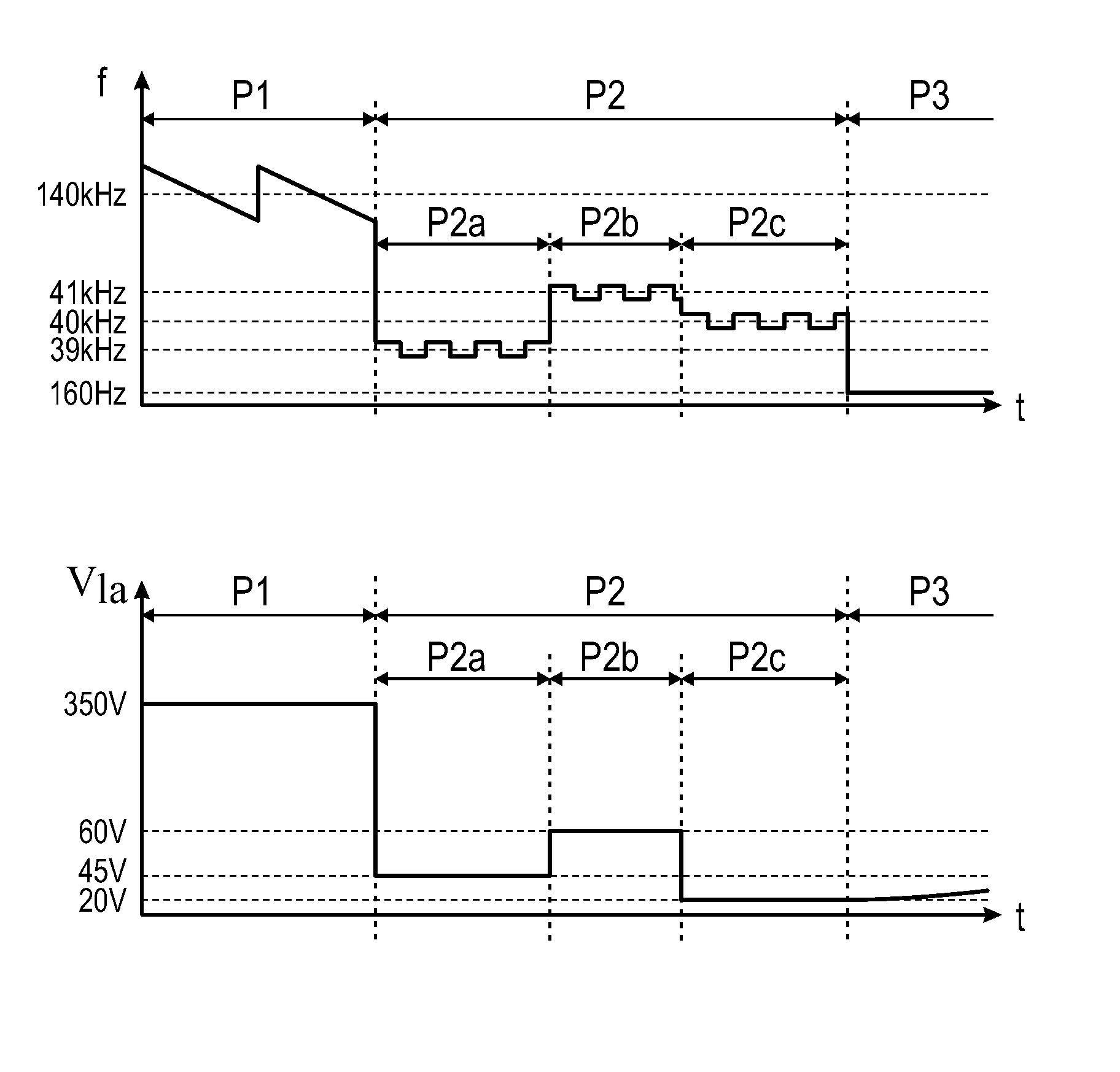
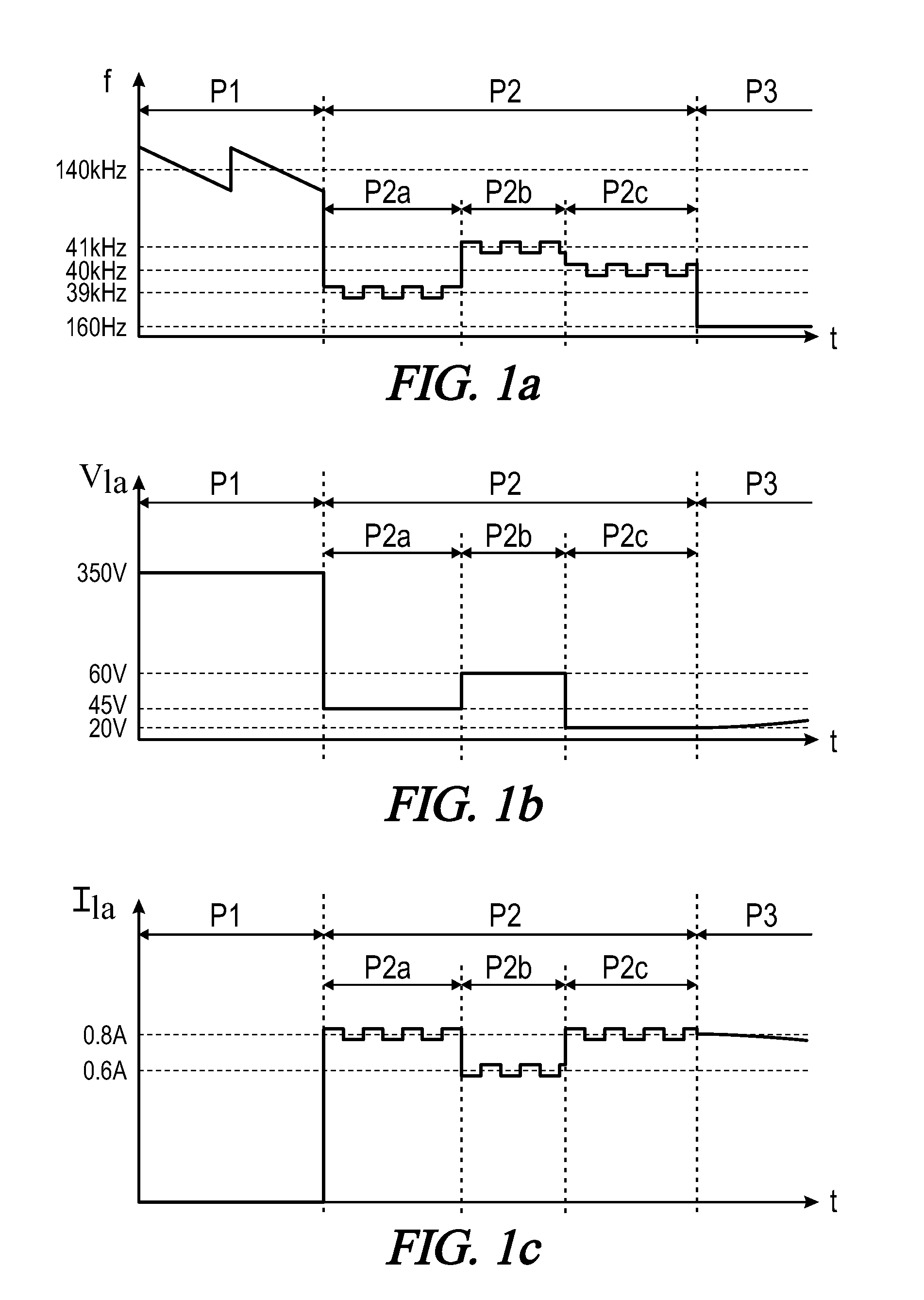
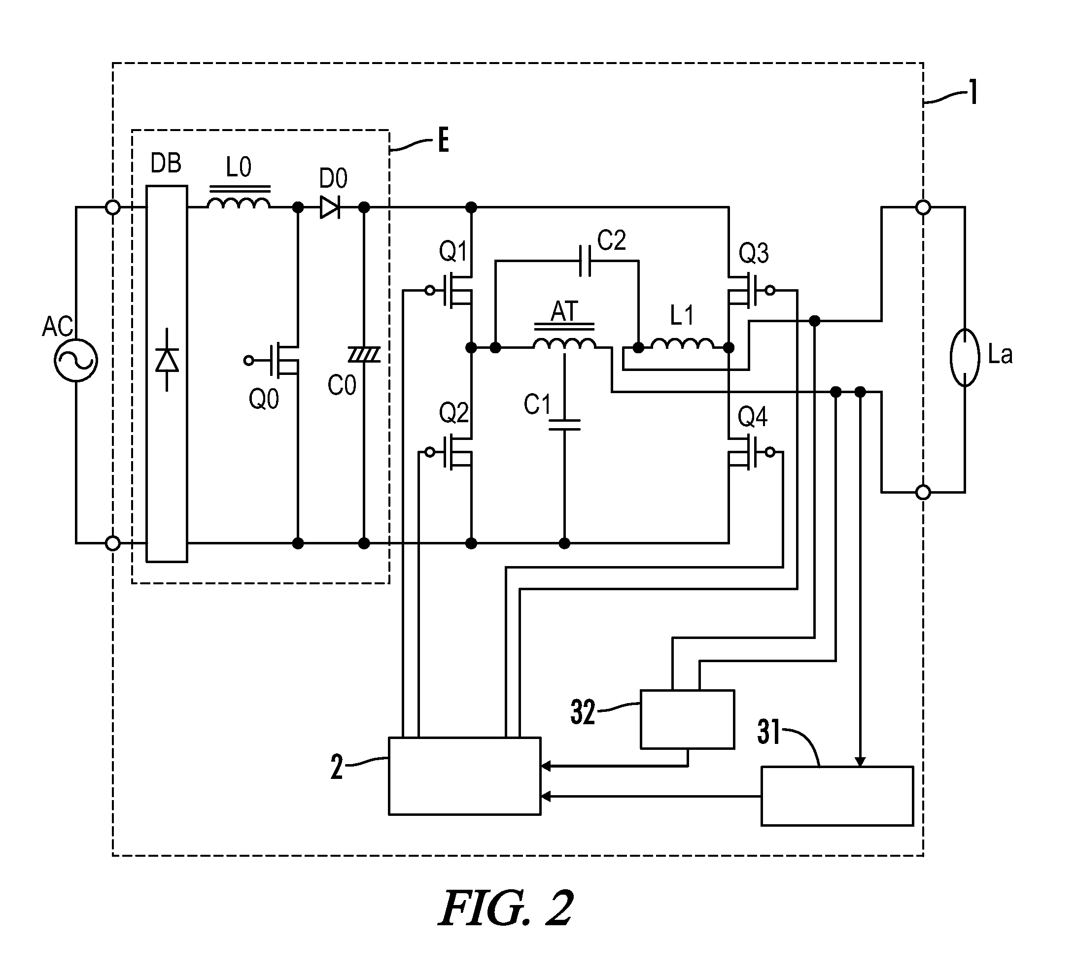
[0020]In accordance with the present invention, a discharge lamp ballast is provided to optimize an output current to the discharge lamp during a filament heating operation. The ballast in various embodiments uses a feedback control loop to adjust the output current such that lamp operation is stabilized and excessive stresses on circuit components are substantially reduced, regardless of the characteristics or type of circuit components and discharge lamp used.

Problems solved by technology

Accordingly, when values for the operation frequency f in the filament heating operation are predetermined, lamp current may be too low in the filament heating operation and the light output from the discharge lamp La in the subsequent normal operation is therefore not stabilized, or conversely an excessive lamp current may flow and undesirable electric stresses may be applied to the circuit components and the discharge lamp La.

Method used


Image

  • Electronic ballast with feedback current control for preheating of lamp filaments
  • Electronic ballast with feedback current control for preheating of lamp filaments
  • Electronic ballast with feedback current control for preheating of lamp filaments

Examples


Embodiment Construction

[0039]Throughout the specification and claims, the following terms take at least the meanings explicitly associated herein, unless the context dictates otherwise. The meanings identified below do not necessarily limit the terms, but merely provide illustrative examples for the terms. The meaning of “a,”“an,” and “the” may include plural references, and the meaning of “in” may include “in” and “on.” The phrase “in one embodiment,” as used herein does not necessarily refer to the same embodiment, although it may.

[0040]The term “coupled” means at least either a direct electrical connection between the connected items or an indirect connection through one or more passive or active intermediary devices.

[0041]The term “circuit” means at least either a single component or a multiplicity of components, either active and / or passive, that are coupled together to provide a desired function.

[0042]The term “signal” means at least one current, voltage, charge, temperature, data or other signal.

[0...


PUM


Abstract

A discharge lamp ballast is provided for powering a discharge lamp with feedback filament heating control. A startup circuit is coupled between output terminals of a DC-AC power converter together with a discharge lamp. A lamp current detection circuit and a lamp voltage detection circuit detect output signals to the lamp. A control circuit controls the switching elements and generates an operating frequency in accordance with a startup operation to generate a high voltage output from the startup circuit and ignite the discharge lamp, a filament heating operation wherein the operating frequency is controlled so as to set the amplitude of the output current detected by the lamp current detection circuit to a target current amplitude based on the amplitude of the output voltage detected by the lamp voltage detection circuit, and a steady-state operation wherein the operating frequency is decreased to maintain a stable light output from the discharge lamp.

Description

[0001]A portion of the disclosure of this patent document contains material that is subject to copyright protection. The copyright owner has no objection to the reproduction of the patent document or the patent disclosure, as it appears in the U.S. Patent and Trademark Office patent file or records, but otherwise reserves all copyright rights whatsoever.CROSS-REFERENCES TO RELATED APPLICATIONS[0002]This application claims benefit of the following patent application(s) which is / are hereby incorporated by reference: Japan Patent Application No. 2009-041505, filed Feb. 24, 2009.STATEMENT REGARDING FEDERALLY SPONSORED RESEARCH OR DEVELOPMENT[0003]Not ApplicableREFERENCE TO SEQUENCE LISTING OR COMPUTER PROGRAM LISTING APPENDIX[0004]Not ApplicableBACKGROUND OF THE INVENTION[0005]The present invention relates to an electronic ballast for powering a discharge lamp and an illumination fixture incorporating the same.[0006]Referring to FIG. 12, an example is shown of a discharge lamp ballast f...

Claims


Application Information

Patent Timeline
Patent Type & Authority Patents(United States)
IPC IPC(8): H05B41/36
CPCH05B41/2988H05B41/2883H05B41/388Y02B20/00
Inventor HASEGAWA, JUNICHIMATSUZAKI, NOBUTOSHI
Owner PANASONIC CORP
Why Eureka
Try Eureka