Pulse period measurement method

a measurement method and pulse technology, applied in the field of pulse period measurement method, can solve the problems of increasing the processing delay dl, reducing the trackability and stability of operation in variable measurement values of the pulse period. , to achieve the effect of improving the stability of the motor drive control, improving the accuracy of the measurement, and reducing the processing delay tim

Active Publication Date: 2013-03-19
SEMICON COMPONENTS IND LLC
View PDF8 Cites 0 Cited by
  • Summary
  • Abstract
  • Description
  • Claims
  • Application Information

AI Technical Summary

Benefits of technology

[0011]The above processing delay is given by the product of the period τCLK of the reference clock CLK and nD. Conventionally, the period τCLK and nD are set to respective constant values within the range Rω of the rotational speed ω being controlled. Therefore, the magnitude of the processing delay DL remains constant substantially within that range Rω without dependence on ω. Here, the frequency of the chattering also varies in accordance with the frequency of the pulse signal PI, and the period of the chattering at the lower limit ω of the range Rω may become the longest. Therefore, if nD, is set so that no determination is made that the chattering at the lower limit is a regular pulse, then chattering at any ω within the range of Rω can be eliminated. In this conventional arrangement, as the rotation of the motor is faster and the pulse period is shorter, the effect of the above-described processing delay DL is greater, and the above-described problem becomes more significant.
[0012]The present invention was made in order to solve the above problem, and the invention provides a pulse period measurement method that can measure a pulse period with good precision and with little processing delay time, and therefore makes possible the improvement of stability in motor speed control in which this method is used.

Problems solved by technology

Therefore, there was a problem of variability in the measurement values of the pulse period due to the variability of the chattering duration period.
The timing for acquiring the pulse period is delayed by that amount, and this may lead to problems such as decreases in the trackability and stability of operation in motor drive control.
In this conventional arrangement, as the rotation of the motor is faster and the pulse period is shorter, the effect of the above-described processing delay DL is greater, and the above-described problem becomes more significant.

Method used


Image

  • Pulse period measurement method
  • Pulse period measurement method
  • Pulse period measurement method

Examples


Embodiment Construction

[0024]Embodiments of the present invention (henceforth, “embodiments”) are explained below with reference to the drawings.

[Controller Structure]

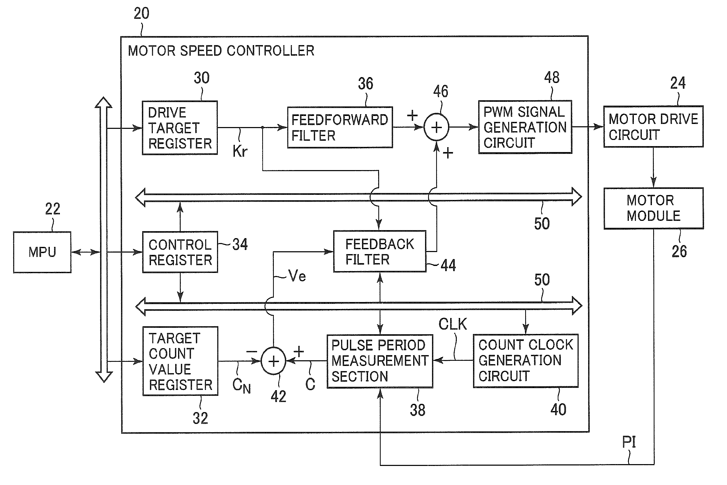
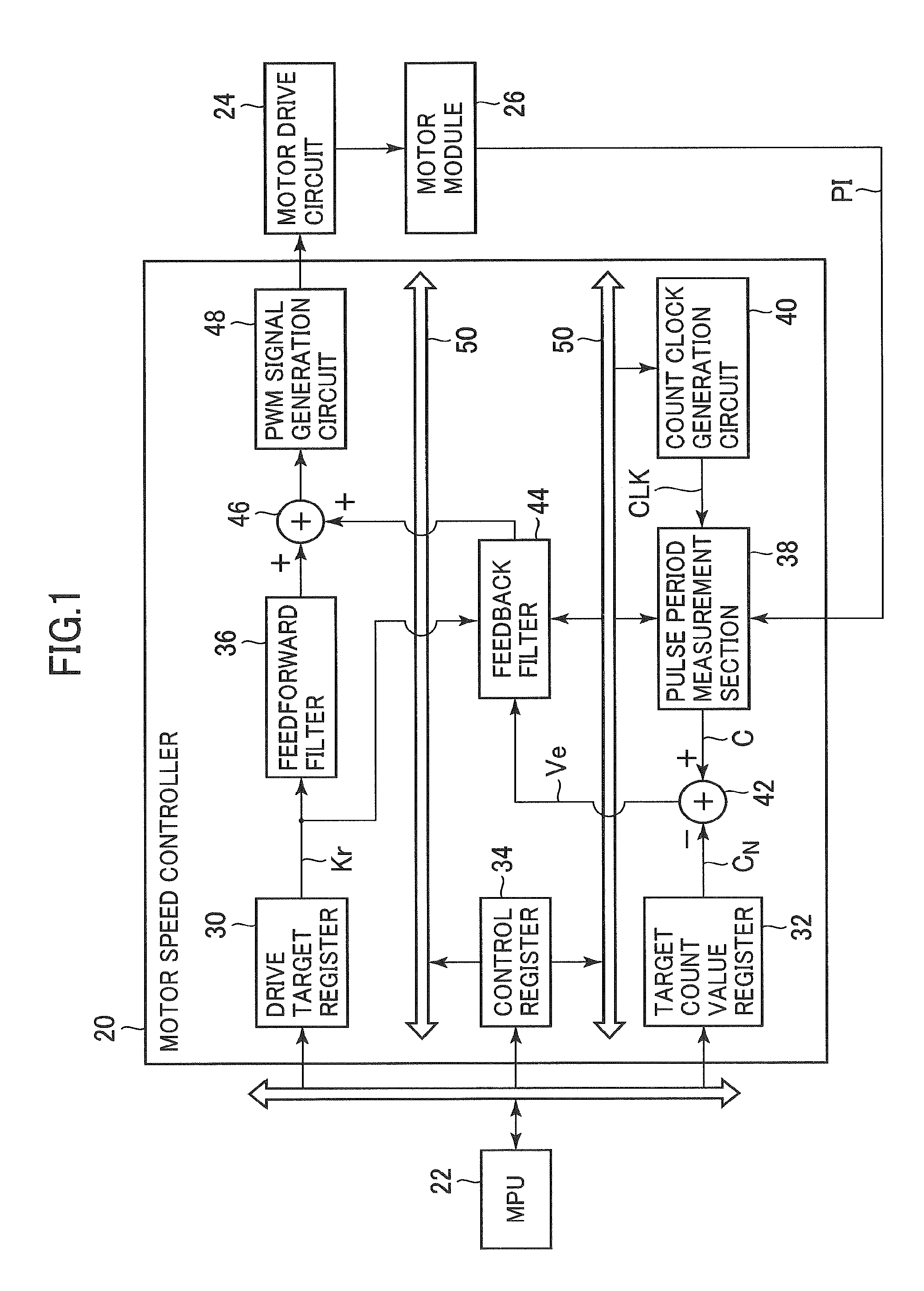
[0025]FIG. 1 is a schematic block diagram illustrating the functional structure of a motor speed controller 20 according to an embodiment of the present invention. The motor speed controller 20 is set parameters such as control target values from an MPU (Micro Processing Unit) 22, and generates a PWM (Pulse Width Modulation) signal for a motor drive circuit 24. The motor drive circuit 24 has an H bridge circuit, and converts the PWM signal from the motor speed controller 20 to a drive signal for a motor module 26 by using the H bridge circuit. The motor module 26 includes a DC motor, a drive mechanism, and an encoder. The drive mechanism, for example, is a zoom mechanism of a camera. The DC motor rotates at a rotational speed that is substantially proportional to the voltage of the drive signal from the motor drive circuit 24, and can switch...


PUM


Abstract

The effect of chattering on the measurement of the pulse period is reduced. The pulse period representing the rise interval of target pulses appearing in a pulse signal PI is measured. The pulse signal PI is sampled in synchronization with a measurement clock CLK. Measurement of a designated inhibition period is started in synchronization with the fall of the signal PI. Measurement of the current pulse period is completed and measurement of a new pulse period is started if the inhibition period has elapsed at the rise of the signal PI. Counting of the current pulse period is continued if the inhibition period has not elapsed.

Description

CROSS-REFERENCE TO RELATED APPLICATION[0001]The present application claims priority from Japanese application JP 2009-012795 filed on Jan. 23, 2009, the content of which is hereby incorporated by reference into this application.BACKGROUND OF THE INVENTION[0002]1. Field of the Invention[0003]The present invention relates to a method of measuring a period of a pulse in which noise such as chattering may occur in the pulse end sections.[0004]2. Description of the Related Art[0005]The speed of a motor can be controlled by obtaining from a motor module a pulse signal PI in which the period varies in accordance with the rotational speed ω of the motor. A motor speed controller measures the period of the pulses appearing in the pulse signal, detects the rotational speed ω of the motor from that period, and drives the motor so that the rotational speed ω is brought to a target value.[0006]Chattering may occur at the edges (pulse ends) of this pulse signal, that is, at the timing when the si...

Claims


Application Information

Patent Timeline
Patent Type & Authority Patents(United States)
IPC IPC(8): H03K5/05H02P6/06
CPCG05B21/02G01R23/15
Inventor TAKAI, KAZUMASA
Owner SEMICON COMPONENTS IND LLC
Why Eureka
Try Eureka