

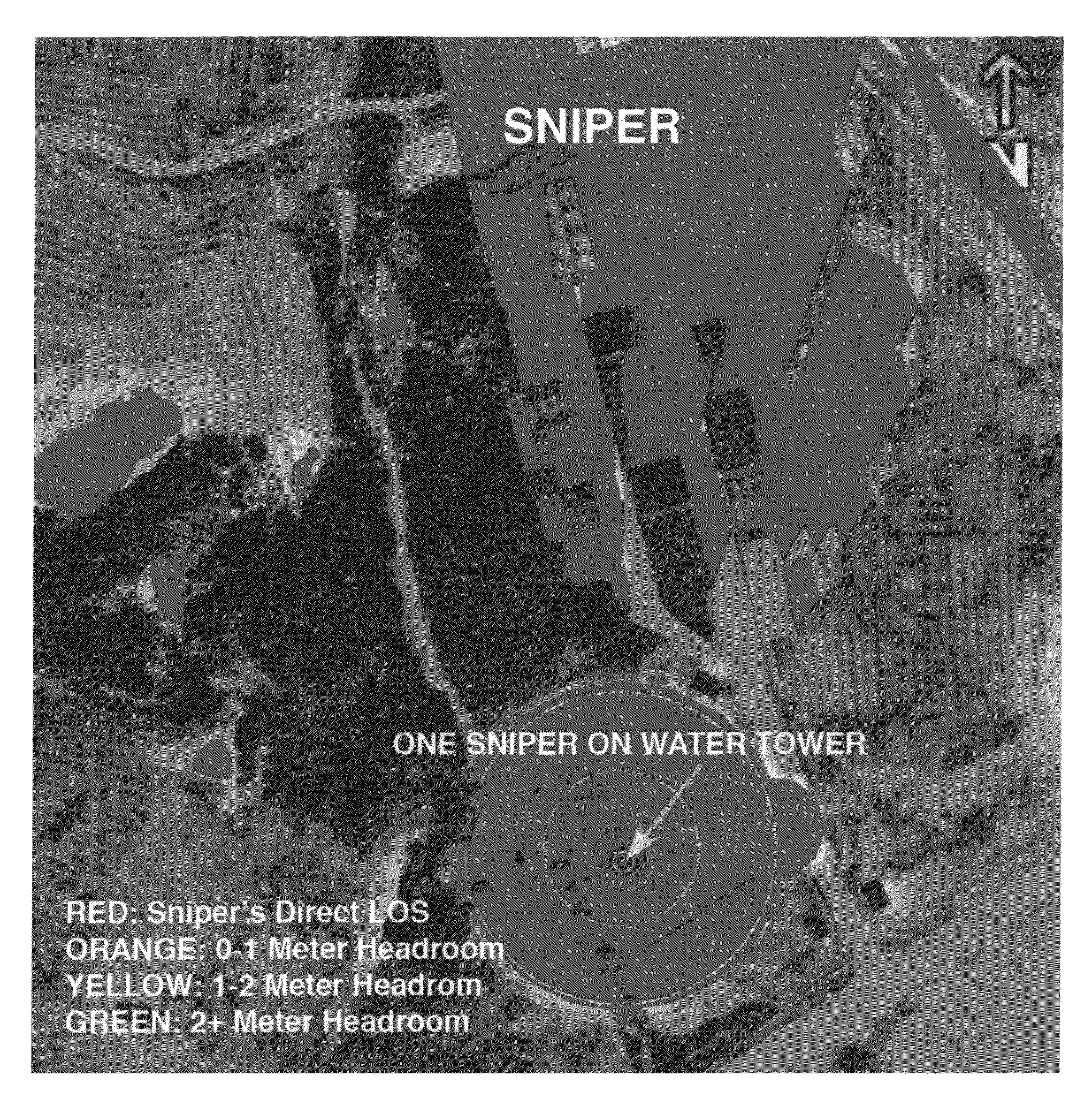
Real-time lines-of-sight and viewsheds determination system
a determination system and real-time line of sight technology, applied in the field of real-time linesof sight and viewshed determination system, can solve the problems of not allowing real-time changes of the user's or the sniper's location, and old methods are limited to a stationary sniper, target, or observer
- Summary
- Abstract
- Description
- Claims
- Application Information
AI Technical Summary
Benefits of technology
Problems solved by technology
Method used
Image

Examples
Embodiment Construction
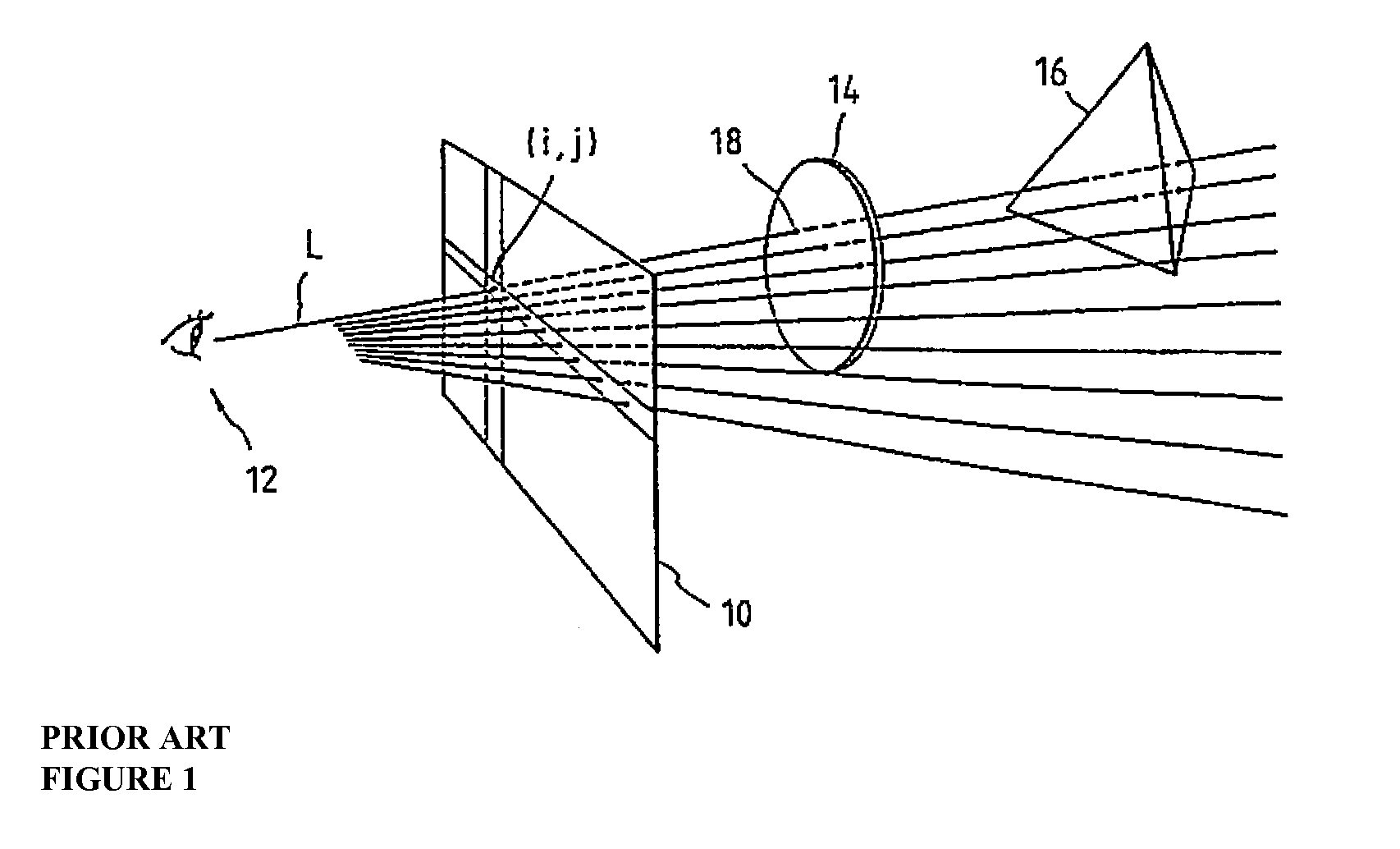
[0031]The present invention employs ray tracing, e.g. as described in U.S. Pat. No. 4,865,423, by Akio Doi, issued Sep. 12, 1989, and in Turner Whitted, “An Improved Illumination Model for Shaded Display”, Communications of the ACM, Vol. 23, No. 6, pp. 343-49 (June 1980), both of which are incorporated herein by reference. Ray tracing is also described in Rob Cook and Ken Torrance, “A Reflectance Model for Computer Graphics”, ACM Transactions on Graphics, Vol. 1, No. 1 (January 1982), also incorporated herein by reference.
[0032]Ray tracing, shown in FIG. 1, starts with a ray L (Line of Sight, or “LOS”), emitted from a viewpoint 12, that is posited for each pixel (I,j) on screen 10 (matched with a plane of projection), and the surfaces of objects intersecting ray L are searched. Of objects 14 and 16, the first intersected by ray L and the first seen is object 14 whose intersecting surface is closer to the viewpoint.
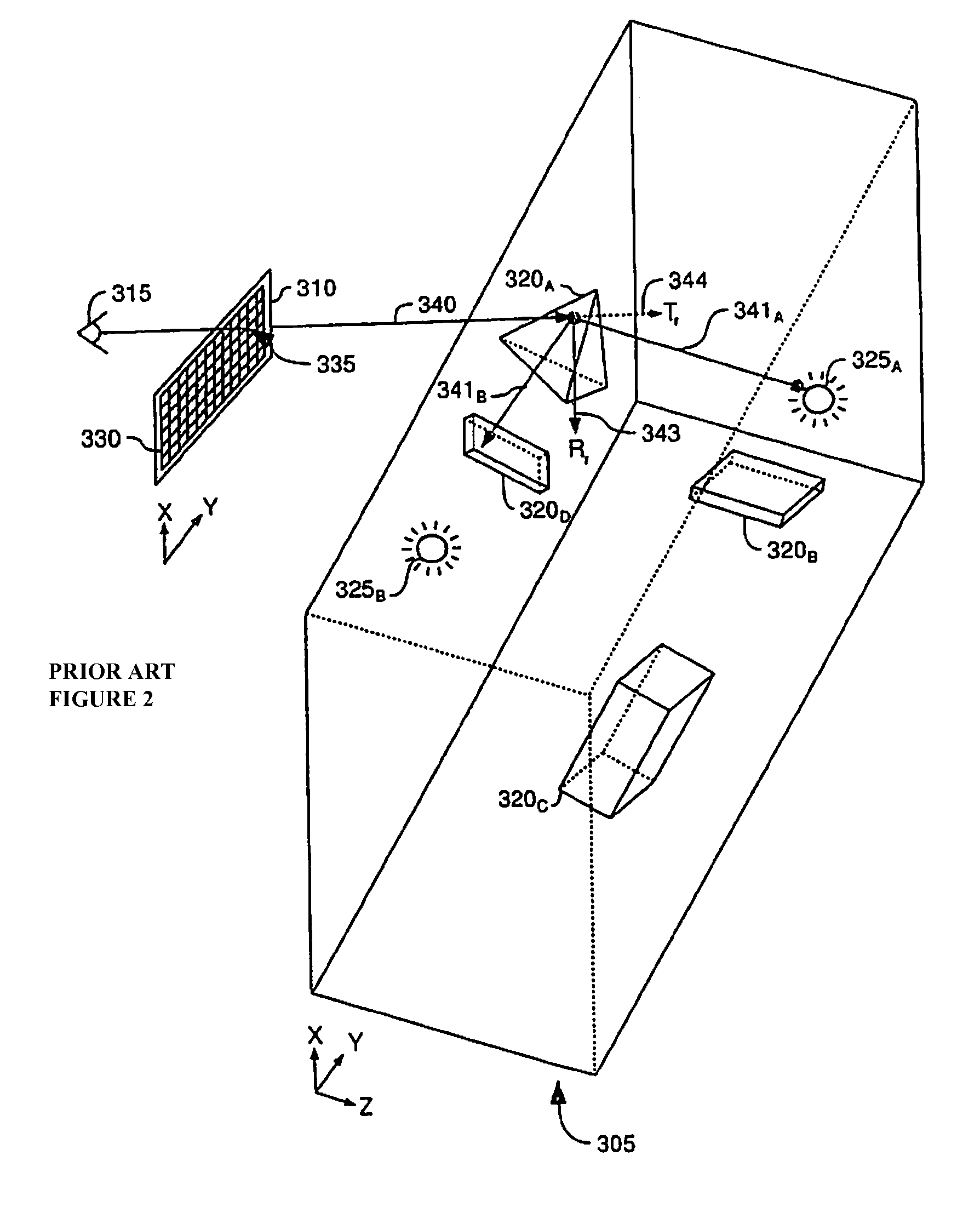
[0033]Another description of ray tracing is found in US Patent Applic...
PUM
 Abstract
Description
Claims
Application Information