
Speckle reduction using beam splitting with birefringent wedge in laser scanning display systems

a laser scanning display system and beam splitting technology, applied in the field of display systems, can solve the problems of degrading the quality of the displayed image, causing the speckle effect to increase, and the solid-state light source to produce unwanted artificial effects, so as to reduce the combined speckle effect and reduce the effect of speckle

Active Publication Date: 2013-03-19
TEXAS INSTR INC
View PDF11 Cites 13 Cited by
  • Summary
  • Abstract
  • Description
  • Claims
  • Application Information

AI Technical Summary

Benefits of technology

This approach reduces the speckle effect by averaging out the contrast between speckle patterns perceived by the viewer, resulting in a less noticeable speckle pattern with a 3 dB reduction in contrast ratio, enhancing image quality.

Problems solved by technology

Regardless of certain superior properties over traditional light sources, solid-state light sources may produce unwanted artificial effects, one of which is speckle effect.
In display applications using coherent light, such as light from solid-state illuminators, speckles accompanying the desired image displayed on a screen overlap with the desired image, and thus may significantly degrade the quality of the displayed image.

Method used


Image

  • Speckle reduction using beam splitting with birefringent wedge in laser scanning display systems
  • Speckle reduction using beam splitting with birefringent wedge in laser scanning display systems
  • Speckle reduction using beam splitting with birefringent wedge in laser scanning display systems

Examples


Embodiment Construction

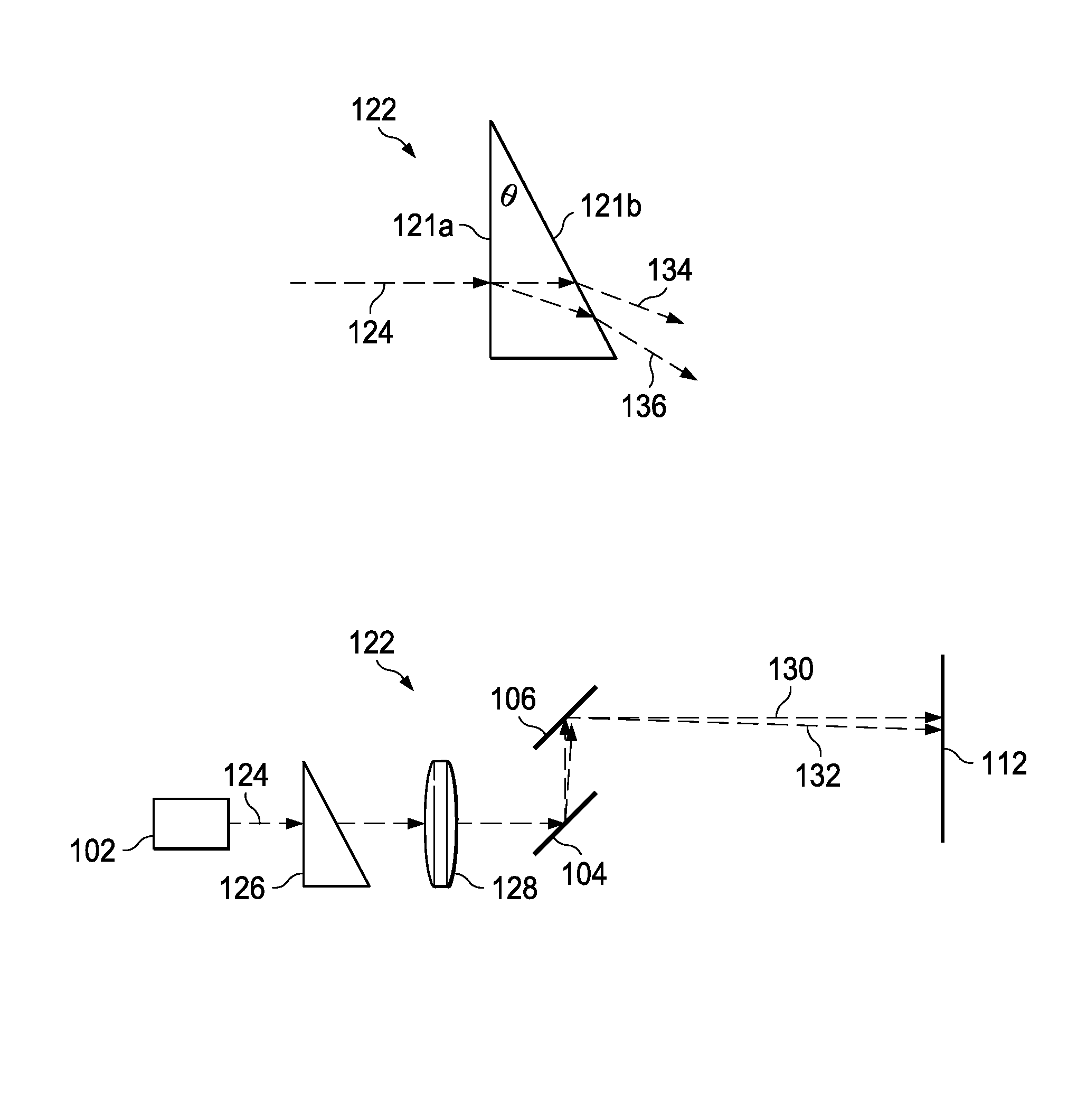
[0011]Disclosed herein is a method of reducing speckle effect in scanning display systems that employ phase-coherent light by driving light of different polarization directions from incoming polarized light; and using the derived light for producing images in the scanning display systems. The speckle reduction method for use in scanning display systems will be discussed in the following, with particular examples, wherein the laser is used as phase-coherent light in scanning display systems. However, it will be appreciated by those skilled in the art that the following discussion is for demonstration purpose, and should not be interpreted as a limitation. Other variations within the scope of this disclosure are also applicable. For example, the method is also applicable to scanning display systems that employ other types of phase-coherent light.

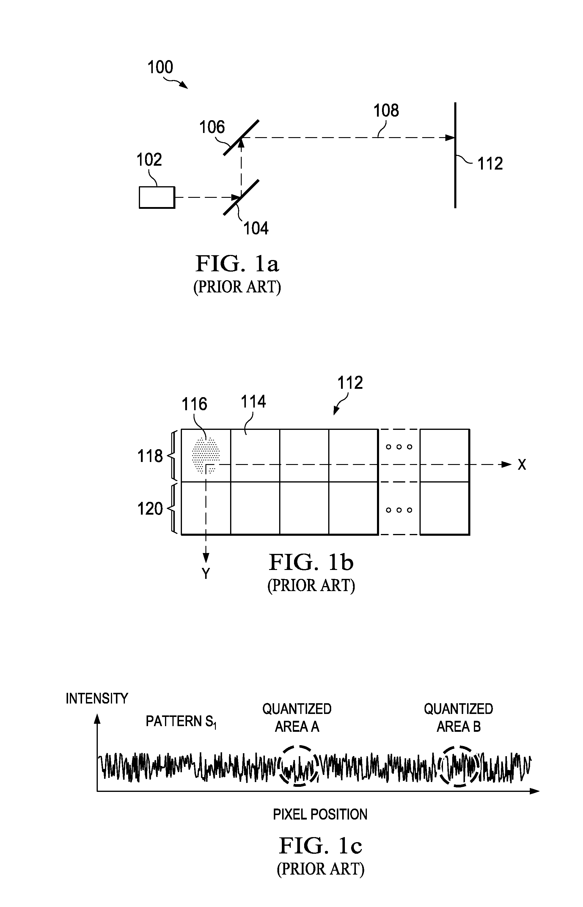
[0012]Referring to the drawings, FIG. 1a diagrammatically illustrates a typical laser-scanning display system 100 in the art. Laser from lase...


PUM


Abstract

Speckle effect in scanning display systems that employs polarized phase-coherent light is reduced by depolarizing the phase-coherent light using a depolarizer and scanning the depolarized light for producing desired images.

Description

CROSS REFERENCE TO RELATED CASES[0001]This US patent application claims priority from co-pending U.S. provisional patent application Ser. No. 60 / 953,415 filed Aug. 1, 2007, the subject matter of which is incorporated herein by reference in its entirety.TECHNICAL FIELD OF THE DISCLOSURE[0002]The technical field of this disclosure relates to the art of display systems; and more particularly to the art of display system employing phase-coherent light.BACKGROUND OF THE DISCLOSURE[0003]In recent years, lasers and other solid-state light sources capable of producing visible light have drawn significant attention as alternative light sources to traditional light sources for use in imaging systems such as projection systems. This attention has been due to many advantages of these light sources, such as compact size, greater durability, longer operating life, higher efficiency, and lower power consumption.[0004]Regardless of certain superior properties over traditional light sources, solid-s...

Claims


Application Information

Patent Timeline
Patent Type & Authority Patents(United States)
IPC IPC(8): G02B27/28
CPCH04N9/3161G02B27/48
Inventor GRASSER, REGIS
Owner TEXAS INSTR INC
Learn More