Device and method for representing the direction of action of a working means

Inactive Publication Date: 2010-09-28
MTU AERO ENGINES GMBH
View PDF27 Cites 8 Cited by
  • Summary
  • Abstract
  • Description
  • Claims
  • Application Information

AI Technical Summary

Benefits of technology

[0004]An object of the present invention is therefore to enable continuous measuring and exact control of the

Problems solved by technology

No possibilities are known at the present time that permit a visualization of the directions of action of tools or invisible rays, for example X-rays of an X-ray diffractometer, during operation.
The requisite devices require a large amount of space and are of elaborate construction, since direct access is needed to the spatial directi

Method used


Image

  • Device and method for representing the direction of action of a working means
  • Device and method for representing the direction of action of a working means

Examples


Example

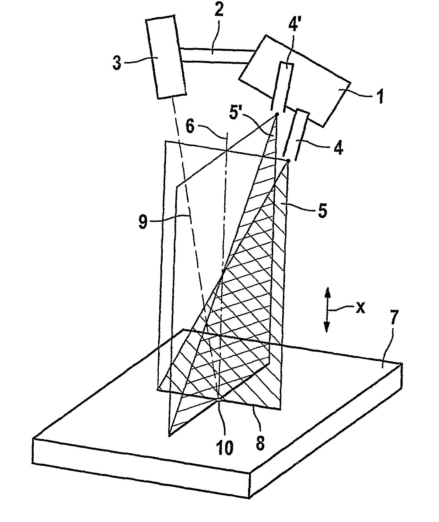
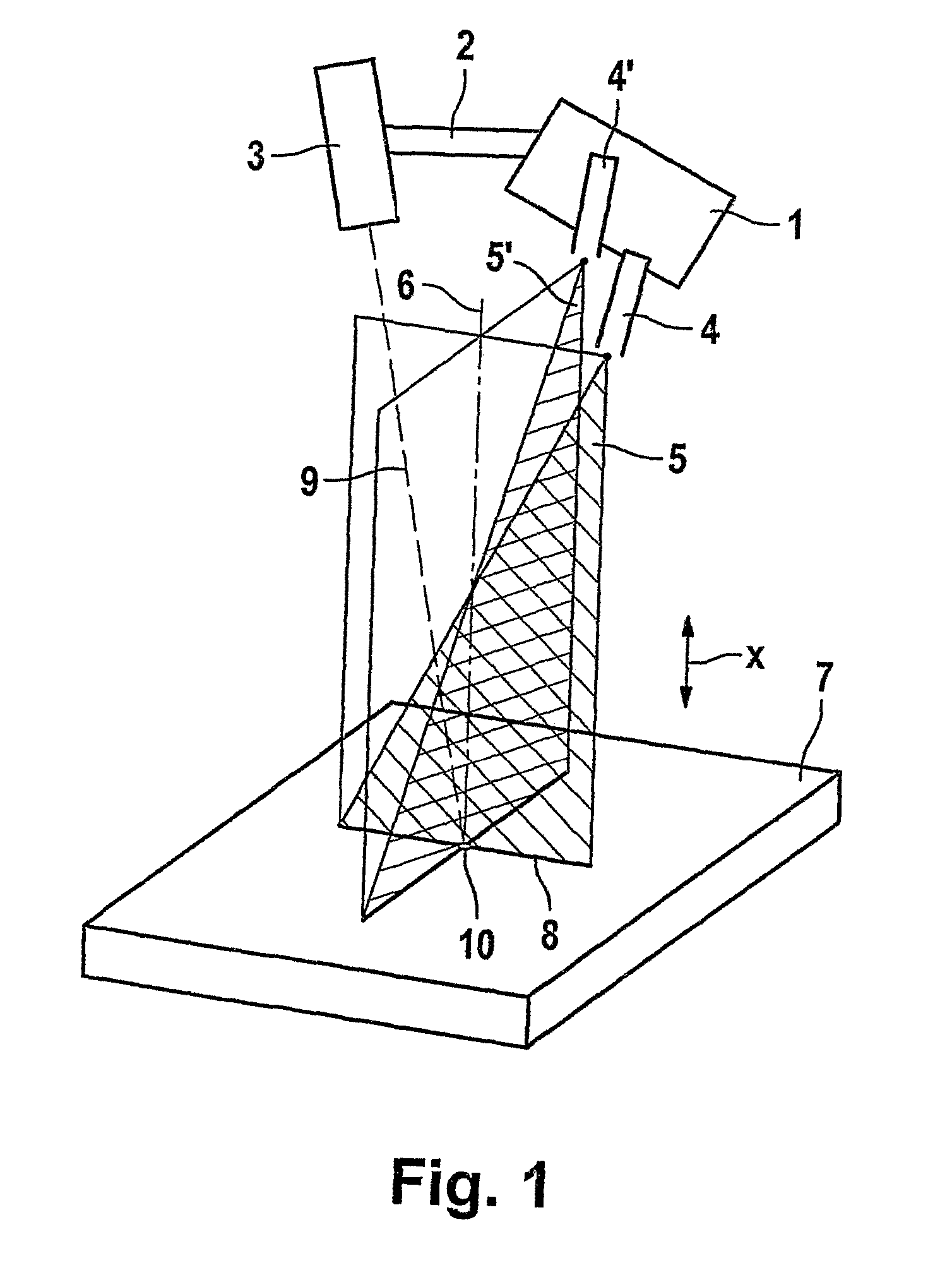
[0016]FIG. 1, the only FIGURE, schematically shows in a three-dimensional view the structure of a device according to the present invention for representing direction of action 9 of a working means 3. Working means 3 may be, for example, a tool, for example for mechanically processing a component 7, or a radiation source, or a radiation receiver for X-rays with which component 7 is to be examined. In particular, working means 3 may be a robot-controlled X-ray diffractometer, whose beam direction as the direction of action 9 to be monitored is to be represented continuously.

[0017]To that end, the device has a first light source 4 for generating a first beam 5 and a second light source 4′ for generating an additional beam 5′. Both light sources 4, 4′ are adjustably attached to a common optical visualizing unit 1, and generate flat beams 5, 5′. Light sources 4, 4′, which are in particular in the form of laser line generators, are configured using the adjusting possibilities on visualiz...


PUM


Abstract

A device for representing the direction of action (9) of a working mechanism (3), in particular a tool or a radiation source and/or a radiation emitter, for example, of X-rays is provided. The device includes a first light source (4) which is used to produce a first beam (5). In order to represent the direction of action in a continuous manner, at least one additional light source (4′) which is used to produce an additional beam (5′) is provided. The light sources (4, 4′) and the working device (3) can be oriented in such a manner that the first beam (5) and the additional beam (5′) have a flat extension and cut in the direction of action (9) of the working mechanism (3). The invention also relates to a corresponding method.

Description

[0001]The present invention relates to a device for representing the direction of action of a working means, in particular a tool or a radiation source or a radiation receiver of X-rays, for example, having a first light source for generating a first ray, and a corresponding method.BACKGROUND[0002]In developing, manufacturing, and testing today's products, high demands are placed on the technologies used to achieve the desired manufacturing accuracy. Products of this type for which the demands on production accuracy are very high include, for example, turbine engines. In particular in the area of manufacturing and testing technology, the positionability of tools or measuring instruments, for example, X-ray diffractometers, with respect to the components is of decisive importance. To achieve high product quality and make manufacturing processes cost-effective, it is important to be able to check the orientation of these working means continuously during operation.[0003]No possibiliti...

Claims


Application Information

Patent Timeline
IPC IPC(8): A61B6/08G01N23/20
CPCB23Q17/2233B23Q17/24
Inventor HESSERT, ROLANDSATZGER, WILHELM
Owner MTU AERO ENGINES GMBH
Why Eureka
Try Eureka