Eureka AIR delivers breakthrough ideas for toughest innovation challenges, trusted by R&D personnel around the world.

Friction-roller type transmission mechanism

a transmission mechanism and friction roller technology, applied in the direction of gearing, transportation and packaging, hoisting equipment, etc., to achieve the effect of shortening the life of the friction roller, reducing the transmission efficiency, and reducing the support stiffness

Inactive Publication Date: 2013-03-26
NISSAN MOTOR CO LTD
View PDF41 Cites 6 Cited by
  • Summary
  • Abstract
  • Description
  • Claims
  • Application Information

AI Technical Summary

Benefits of technology

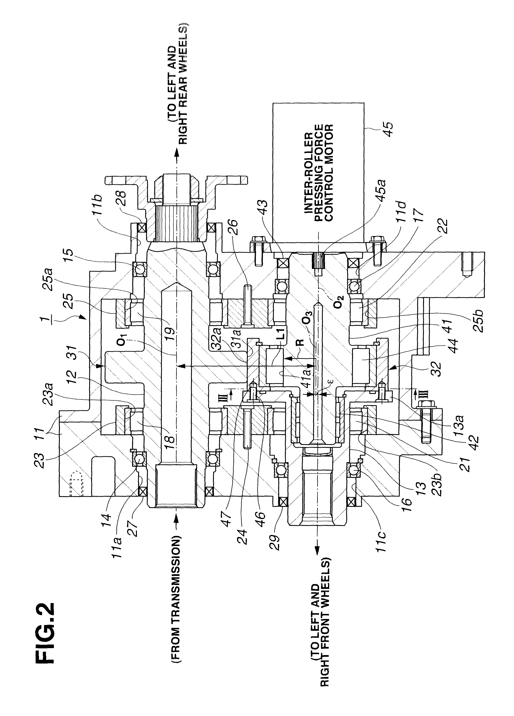
[0008]The following construction allows the bearing supports to bear a radial pressing reaction between the friction rollers. A first bearing support is disposed in a plane perpendicular to an axial direction, which plane contains a portion of the bearing-fitting, wherein the friction roller shaft related to the one of the friction rollers, and a friction roller shaft related to another of the friction rollers are bearing-fitted to the first bearing support. A second bearing support is disposed in a plane opposite to the first bearing support with respect to the friction rollers, wherein the crankshaft related to the one of the friction rollers, and the friction roller shaft related to the other of the friction rollers are bearing-fitted to the second bearing support. This construction allows the first and second bearing supports to bear the inter-friction-roller radial pressing reaction, and thereby serves to avoid a disadvantage that the inter-friction-roller radial pressing is inputted to the housing.
[0010]Each bearing is an assembled product of a lot of parts such as an inner race, an outer race, and a lot of rolling elements between the inner race and outer race. Accordingly, each bearing is lower in support stiffness against the inter-friction-roller radial pressing reaction (smaller in spring constant) than the bearing supports which are usually formed integrally. As a result, the bearing-fitting portion where the crankshaft and the friction roller shaft related to the one of the friction rollers are arranged coaxially with one another to face one another, which transmits the inter-friction-roller radial pressing reaction to the first bearing support through the place where inner and outer bearings that are lower in the support stiffness against the inter-friction-roller radial pressing reaction (smaller in spring constant) are disposed in double layer arrangement, is displaced in the corresponding radial direction by a relatively large amount, due to a large amount of deformation of inner and outer bearings in double layer arrangement under the inter-friction-roller radial pressing reaction, in addition to a small amount of deformation of the bearing support.
[0011]In contrast, each of the other bearing-fitting portions at the first bearing support and second bearing support is provided with a bearing in single arrangement. Each shaft portion which transmits the inter-friction-roller radial pressing reaction to the corresponding bearing support through the bearing in single arrangement, is not displaced in the radial direction by a large amount, even when a small amount of deformation of the bearing in single arrangement due to the inter-friction-roller radial pressing reaction is added to a small amount of deformation of the bearing support. As a result, the relatively large radial displacement of the bearing-fitting portion where the crankshaft and the friction roller shaft related to the one of the friction rollers are arranged coaxially with one another to face one another, causes unbalanced contact between frictional contact portions of the friction rollers, and thereby shortens the life of the friction rollers, and lowers the transmission efficiency, which is undesirable anyway.
[0012]It is an object of the present invention to provide a friction roller type transmission mechanism which is capable of solving the problem described above about decrease in the life of the friction rollers and decrease in the transmission efficiency, wherein the large radial displacement of the bearing-fitting portion where the crankshaft and the friction roller shaft related to the one of the friction rollers are arranged coaxially with one another to face one another, due to the large amount of deformation of the inner and outer bearings in double layer arrangement, is reduced by a measure for the bearing support, so as to prevent unbalanced contact between the friction rollers.

Problems solved by technology

However, in such a case where the bearing supports on both sides of the friction rollers in the axial direction are identical to one another in the support stiffness against the inter-friction-roller radial pressing reaction, friction roller type transmission mechanisms that are capable of controlling the inter-friction-roller radial pressing force are subject to the following structural problem, although friction roller type transmission mechanisms in which the inter-friction-roller radial pressing force is set constant as in patent document 1.

Method used


Image

  • Friction-roller type transmission mechanism
  • Friction-roller type transmission mechanism
  • Friction-roller type transmission mechanism

Examples


Embodiment Construction

[0024]According to the friction roller type transmission mechanism according to the present invention, the construction that support stiffness of the first bearing support against the radial pressing reaction between the friction rollers is higher than that of the second bearing support, serves to solve the problem described above about decrease in the life of the friction rollers and decrease in the transmission efficiency by preventing unbalanced contact between the friction rollers, wherein even when the bearing-fitting portion where the crankshaft and the friction roller shaft related to the one of the friction rollers are arranged coaxially with one another to face one another is displaced in the corresponding radial direction by a relatively large amount, due to a large amount of deformation of the inner and outer bearings in double layer arrangement under the inter-friction-roller radial pressing reaction, in addition to deformation of the first bearing support, the large rad...


PUM


Abstract

Under control of rotation of a crankshaft 41, a friction roller 32 is pressed against a friction roller 31 in a radial direction, so as to achieve torque transmission between the rollers 31, 32. An inter-roller radial pressing reaction is canceled as an internal force in bearing supports 23, 25, with no input to a housing 11. The reaction causes a radial displacement of a bearing-fitting portion provided with inner and outer bearings 21, 42 in double layer arrangement, wherein the radial displacement is larger than that of a bearing-fitting portion provided with a bearing 18, 19, 22 in single arrangement, so as to cause unbalanced contact between rollers 31, 32. In order to prevent this, support stiffness of bearing support 23 against the inter-friction-roller radial pressing reaction is set higher than that of bearing support 25.

Description

TECHNICAL FIELD[0001]The present invention relates to a friction roller type transmission mechanism wherein a pair of friction rollers that rotate about respective axes parallel to one another are pressed against one another in a radial direction of the friction rollers into frictional contact with one another in one of a direct manner and an indirect manner, to allow power transmission between the friction rollers.BACKGROUND OF THE INVENTION[0002]Conventionally, as disclosed in a patent document 1, a friction roller type transmission mechanism is known in which in order to prevent a radial pressing reaction from being directly inputted to a housing when the friction rollers are in frictional contact with one another, shafts of the friction rollers are bearing-fitted to common bearing supports on both sides of the friction rollers in an axial direction, wherein the bearing supports are attached to the housing, so that the friction rollers are rotatably supported with respect to the ...

Claims


Application Information

Patent Timeline
Patent Type & Authority Patents(United States)
IPC IPC(8): F16H21/14
CPCF16H13/02B60K17/344F16H13/10Y10T74/18392
Inventor MORI, ATSUHIROKARIYA, TAKESHIKIYOHARA, SHINJI
Owner NISSAN MOTOR CO LTD
Why Eureka
Eureka Blog
Learn More