Engine device

Active Publication Date: 2020-10-01
HONDA MOTOR CO LTD
View PDF0 Cites 1 Cited by
  • Summary
  • Abstract
  • Description
  • Claims
  • Application Information

AI Technical Summary

Benefits of technology

[0020]Thus, according to the present invention, it is possible to provide an engin

Problems solved by technology

However, the engine power equipment described i

Method used


Image

  • Engine device
  • Engine device
  • Engine device

Examples


Example

[0027]In the following, an embodiment of the present invention will be described in detail with reference to the drawings.

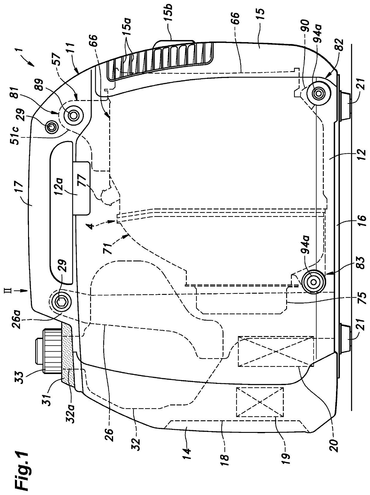
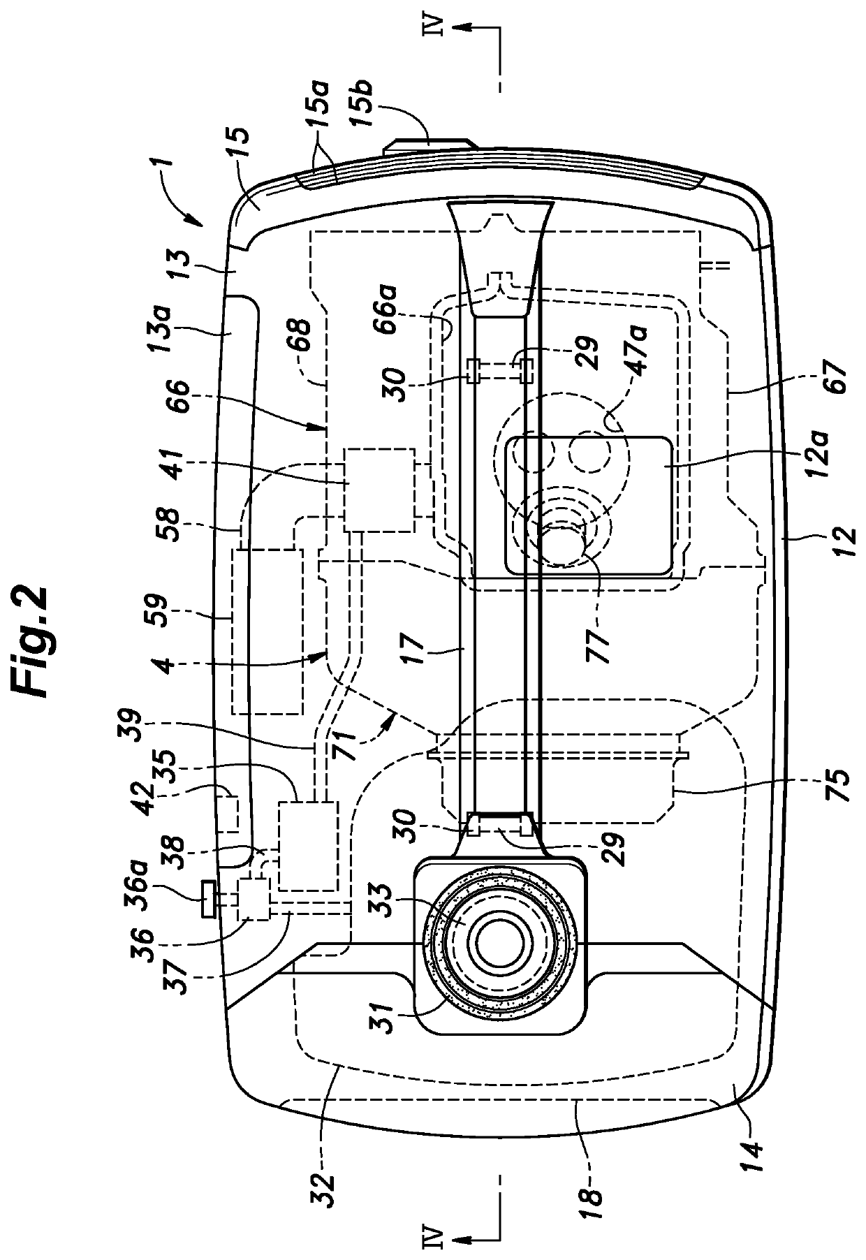
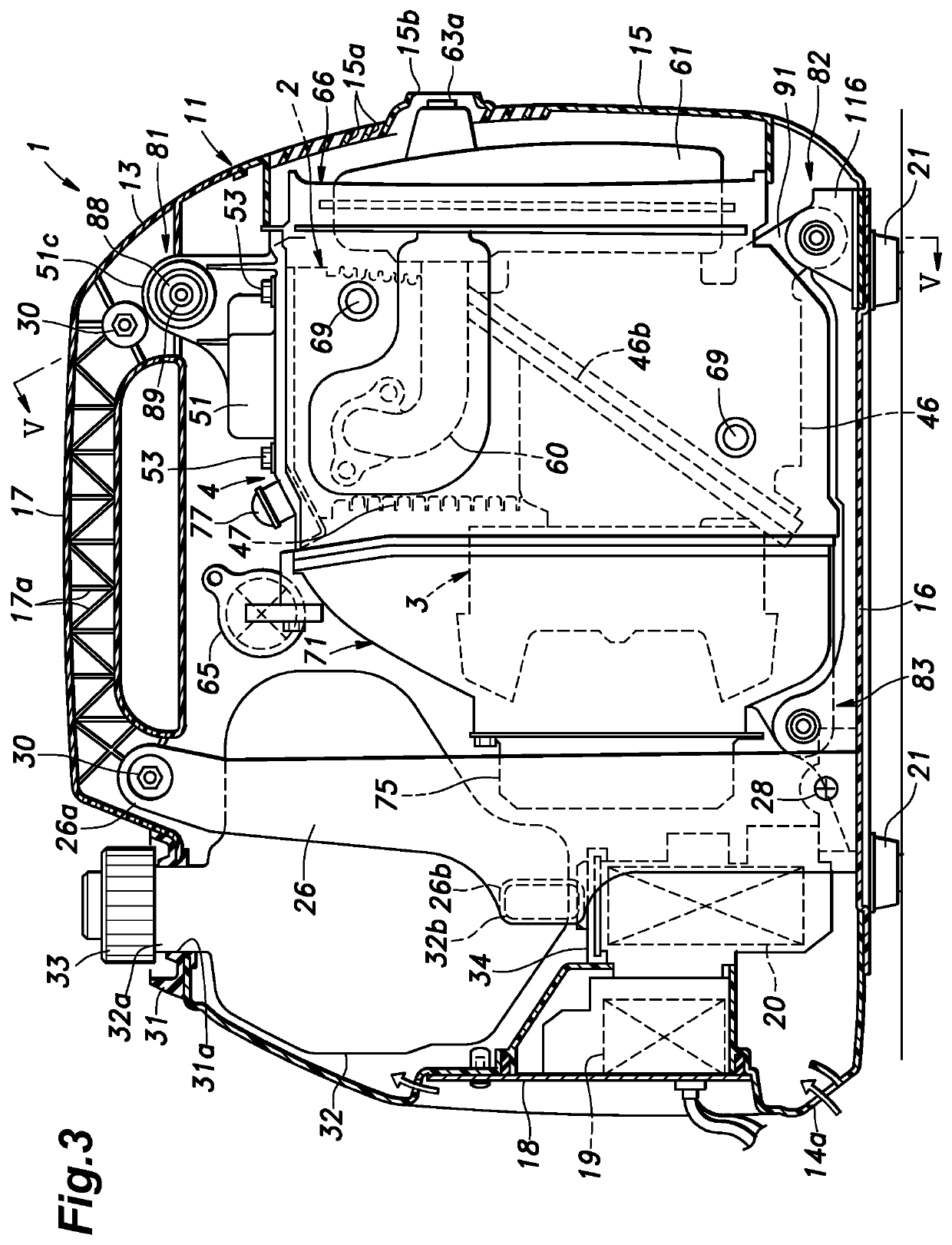
[0028]As shown in FIGS. 1 to 4, an engine generator 1 includes an engine 2 (see FIGS. 3 and 4) and a generator 3 (see FIGS. 3 and 4) as power equipment driven by the engine 2. The engine generator 1 is engine power equipment that drives the generator 3 by the engine 2 to generate electricity. The engine 2 and the generator 3 compose a power generation unit 4 as a power unit and are housed in a case 11. The case 11 is made of synthetic resin and defines an outline of the engine generator 1. In this sense, the engine generator 1 is an engine device including the engine 2 and the case 11.

[0029]The case 11 includes a left side cover 12, a right side cover 13, a front cover 14, a rear cover 15, and an under cover 16. The left side cover 12 and the right side cover 13 are integrally joined to each other, and a carrying handle 17 for carrying the engine generator 1 is f...


PUM


Abstract

Provided is an engine device that can enlarge a space inside a case without lowering support stiffness. An engine (2) is attached to a case (11) via support parts (81, 82). A rear lower portion support part (82), which is one of the support parts, includes an attachment rib (11b) as a mounting part provided in the case (11) and an attachment bracket (91) fastened to a bottom of a crankcase (46) by a fastening bolt (90) and attached to the attachment rib (11b). The fastening bolt (90) penetrates through a through hole (92a) provided in the attachment bracket (91) and is screwed into a screw hole (46e) formed obliquely inward at a corner of the bottom of the crankcase (46).

Description

TECHNICAL FIELD[0001]The present disclosure relates to an engine device including an engine and a case that accommodates the engine.BACKGROUND ART[0002]There is a known portable engine power equipment configured such that an engine and a power equipment driven by the engine are accommodated in a case made of synthetic resin and a carrying handle is provided at an upper part of the case (for example, Patent Document 1). In this engine power equipment, a crankcase, a cylinder block and a cylinder head of the engine are covered by a shroud, and a head cover of the engine is exposed via an opening formed in an upper part of the shroud so as to be elastically supported by the carrying handle of the case. Accordingly, when the carrying handle is grasped and the engine power equipment is lifted, the loads of the engine and the power equipment act directly on the carrying handle.PRIOR ART DOCUMENT (S)Patent Document(S)[0003]Patent Document 1: JP2001-27127ASUMMARY OF THE INVENTIONTask to be ...

Claims


Application Information

Patent Timeline
IPC IPC(8): F02F7/00F01N1/02F01N3/28
CPCF01N1/02F01N3/28F02F7/0082F02F1/00F02F7/00F02B63/048F02F7/0065F02F7/0039
Inventor KONO, SHOHEIKAI, MASASHI
Owner HONDA MOTOR CO LTD
Why Eureka
Try Eureka