Dissolvable tool and method

a tool and tool technology, applied in the direction of fluid removal, sealing/packing, borehole/well accessories, etc., can solve the problems that even in a deformed state, their presence, can still be undesirabl

Active Publication Date: 2013-03-26
BAKER HUGHES HLDG LLC
View PDF135 Cites 113 Cited by
  • Summary
  • Abstract
  • Description
  • Claims
  • Application Information

AI Technical Summary

Problems solved by technology

Although such tools work as intended, their presence, even in a deformed state can still be undesirable.

Method used


Image

  • Dissolvable tool and method
  • Dissolvable tool and method
  • Dissolvable tool and method

Examples


Embodiment Construction

[0023]A detailed description of one or more embodiments of the disclosed apparatus and method are presented herein by way of exemplification and not limitation with reference to the Figures.

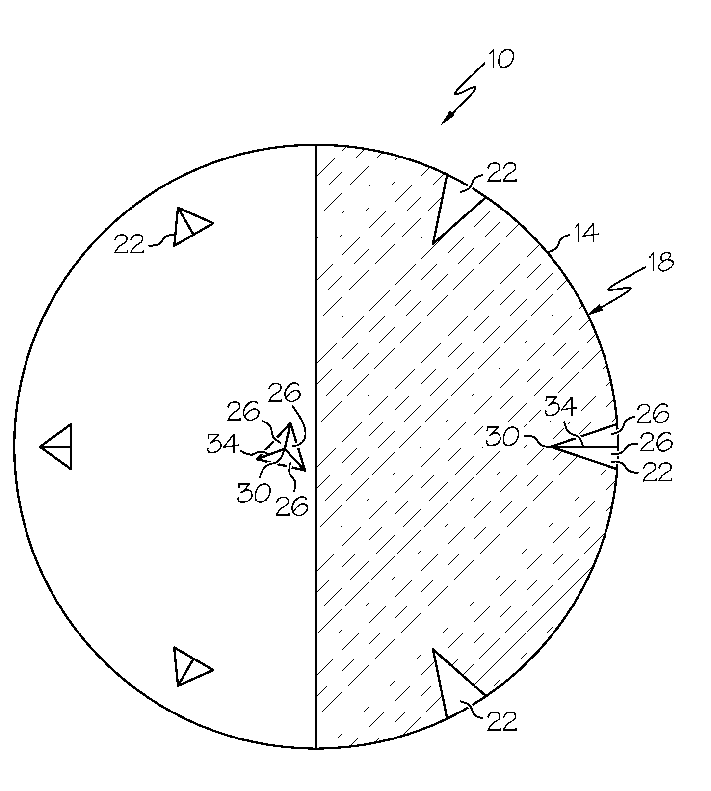
[0024]Referring to FIG. 1, a quarter cross sectional view of an embodiment of a dissolvable tool disclosed herein is illustrated generally at 10. The tool 10, includes a body 14 illustrated in this embodiment as a ball, however, alternate embodiments are contemplated such as, an ellipsoid, a cylinder or a polyhedron, for example. The body 14 has a surface 18 that has a plurality of stress risers 22. The stress risers 22 illustrated herein are indentations, however, alternate embodiments may employ stress risers 22 with other configurations, such as, cracks or foreign bodies, for example. Additionally, alternate embodiments may employ any number of stress risers 22 including embodiments with just a single stress riser 22. The stress risers 22 are configured to concentrate stress at the specific lo...


PUM

PropertyMeasurementUnit
average particle diameteraaaaaaaaaa

Abstract

A method of dissolving a tool includes exposing an outer surface of the tool to an environment reactive with the tool, reacting the tool with the environment, and applying stress to the tool. The method also includes concentrating stress on the tool at stress risers in the outer surface, and initiating fracturing the tool at the stress risers.

Description

CROSS REFERENCE TO RELATED APPLICATIONS[0001]This application contains subject matter related to the subject matter of co-pending applications, which are assigned to the same assignee as this application, Baker Hughes Incorporated of Houston, Tex. and are all being filed on Dec. 8, 2009. The below listed applications are hereby incorporated by reference in their entirety:[0002]U.S. patent application Ser. No. 12 / 633,682, entitled NANOMATRIX POWDER METAL COMPACT;[0003]U.S. patent application Ser. No. 12 / 633,686, entitled COATED METALLIC POWDER AND METHOD OF MAKING THE SAME;[0004]U.S. patent application Ser. No. 12 / 633,688, entitled METHOD OF MAKING A NANOMATRIX POWDER METAL COMPACT;[0005]U.S. patent application Ser. No. 12 / 633,678, entitled ENGINEERED POWDER COMPACT COMPOSITE MATERIAL;[0006]U.S. patent application Ser. No. 12 / 633,683, entitled TELESCOPIC UNIT WITH DISSOLVABLE BARRIER;[0007]U.S. patent application Ser. No. 12 / 633,677 entitled MULTI-COMPONENT DISAPPEARING TRIPPING BALL...

Claims


Application Information

Patent Timeline
Patent Type & Authority Patents(United States)
IPC IPC(8): E21B33/12E21B29/02
CPCE21B23/04E21B23/00E21B41/00E21B23/0413
Inventor AGRAWAL, GAURAVXU, ZHIYUE
Owner BAKER HUGHES HLDG LLC
Why Eureka
Try Eureka