
Multi-core fiber

a fiber and core technology, applied in the field of multi-core fibers, to achieve the effect of ensuring the quality of the fiber

Active Publication Date: 2013-03-26
SUMITOMO ELECTRIC IND LTD
View PDF2 Cites 33 Cited by
  • Summary
  • Abstract
  • Description
  • Claims
  • Application Information

AI Technical Summary

Benefits of technology

[0029]In the multi-core fiber according to the present invention, it is preferable that, in the cladding region, the plurality of cores is added with a twist. For example, the condition that the cores are added with a twist means a condition that a twist is given in an optical fiber drawing or is additionally given after an optical fiber drawing, namely a condition that the plurality of cores are twisted in a circumferential direction with respect to the center axis of fiber. Both of the twist in a specific direction and the twist whose directions are inverted are acceptable. By this, the refractive index of a specific core does not intensively increase even when the multi-core fiber is bent, and then the refractive index increasing can spread. As a result, the effect of cross talk is relieved, it is not necessary to provide a difference of refractive index between cores beyond necessity.

Problems solved by technology

In the multi-core fiber designed without considering a bending, it was discovered that a crosstalk, having a level that there is a problem with transmission and measurement for optical characteristics of each core, is caused by a bending of the multi-core fiber wounded on the bobbin.

Method used


Image

  • Multi-core fiber
  • Multi-core fiber
  • Multi-core fiber

Examples


Embodiment Construction

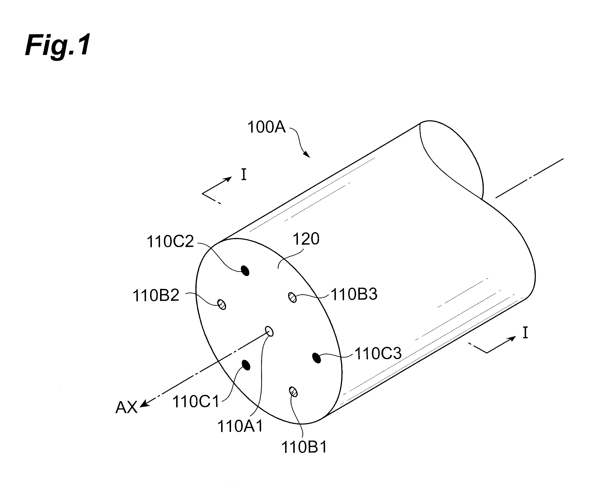
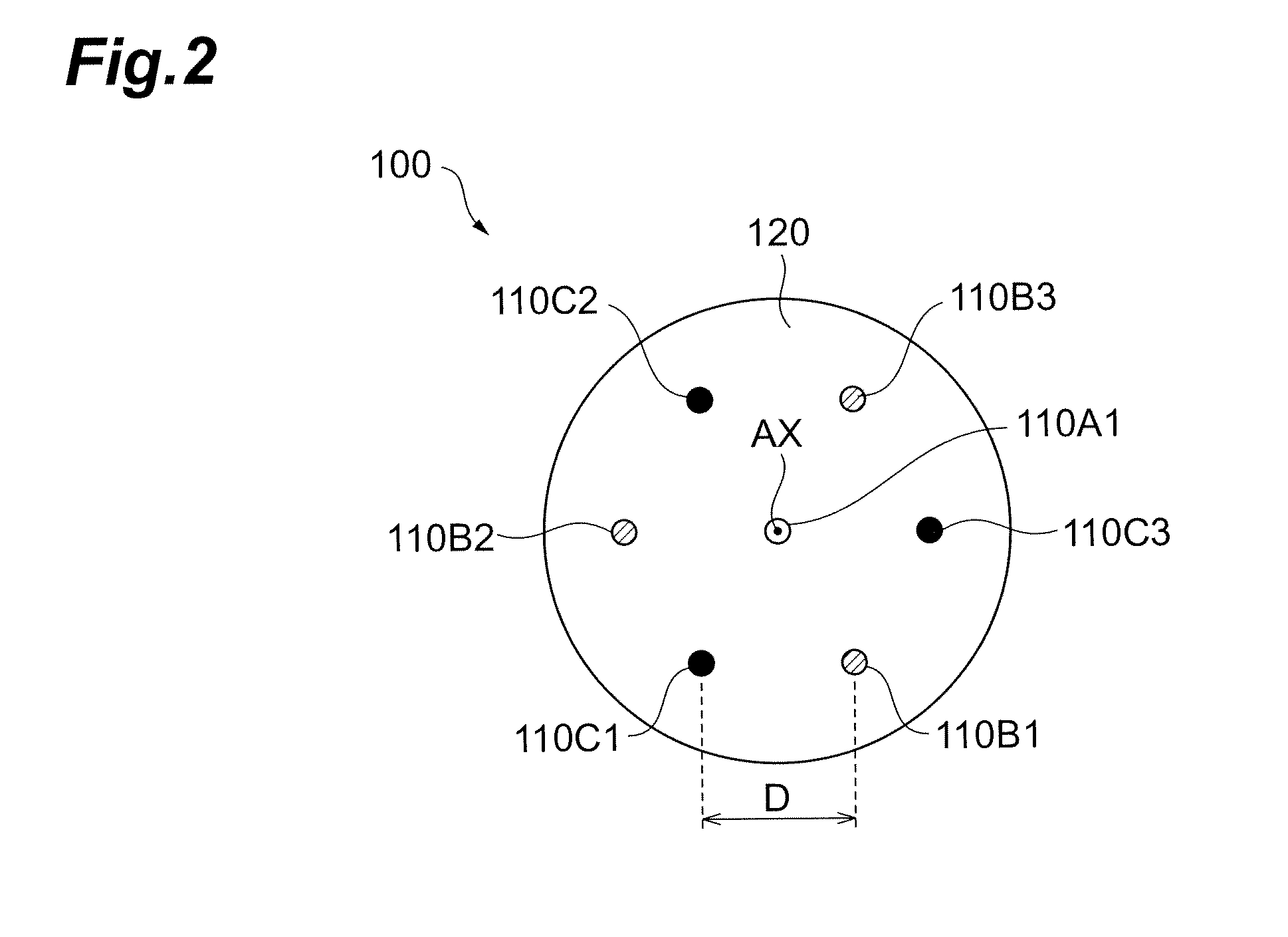
[0042]In the following, embodiments of the multi-core fiber according to the present invention will be explained in detail with reference to FIGS. 1 to 2, and 3A to 9C. In the description of the drawings, identical or corresponding components are designated by the same reference numerals, and overlapping description is omitted.

[0043]First, FIG. 1 is a perspective view showing a structure of an embodiment of the multi-core fiber according to the present invention. FIG. 2 is a view showing a sectional structure along the I-I line of the multi-core fiber shown in FIG. 1.

[0044]As shown in FIG. 1, the multi-core fiber 100A according to the present embodiment comprises seven cores 110A1, 110B1 to 110B3, and 110C1 to 110C3 which respectively extend along a predetermined axis AX and are classified into three types, and a cladding region 120 which surrounds integrally these seven cores. In the multi-core fiber 100A according to the present embodiment, as a core arrangement, the core 110A1 is...


PUM


Abstract

The present invention relates to a multi-core fiber having a structure for effectively suppressing crosstalk increase between cores caused by bending within an allowable range. The multi-core fiber comprises a plurality of types of cores respectively extending along an optical axis and a cladding region, and the effective refractive index of each core is set so that, in all pairs of cores of different types, a relative refractive index difference between an effective refractive index of a core of a certain type and an effective refractive index of a core of another type satisfies a condition regulated according to a core spacing between cores and a bending radius.

Description

CROSS-REFERENCE TO RELATED APPLICATION[0001]This application claims priority to Provisional Application No. 61 / 298,073 filed on Jan. 25, 2010 by the same Applicant, which is hereby incorporated by reference in its entirety.BACKGROUND OF THE INVENTION[0002]1. Field of the Invention[0003]The present invention relates to a multi-core fiber having a plurality of cores respectively extending along a predetermined axis.[0004]2. Related Background Art[0005]Multi-core fibers, constituted so as to integrally surround a plurality of cores with a cladding region in order to realize higher capacity in optical transmission, are known.[0006]For example, in a multi-core fiber described in IEICE Electronics Express, Vol. 6, No. 2, pp. 98-103 (Document 1), when the center-to-center spacing of the cores is 30 μm, concerning the power transfer ratio between cores adjacent to each other, sufficiently small crosstalk can be realized by changing the difference in relative refractive index difference Δ (h...

Claims


Application Information

Patent Timeline
Patent Type & Authority Patents(United States)
IPC IPC(8): G02B6/036
CPCG02B6/02042G02B6/03661G02B6/0365
Inventor HAYASHI, TETSUYA
Owner SUMITOMO ELECTRIC IND LTD
Learn More