Seat for powered aircraft, the seat incorporating means for protecting its passenger in the event of a crash

a technology for aircraft and seats, applied in the field of seats for powered aircraft, can solve the problems of high stress on seats, and achieve the effect of avoiding increasing the size and weight of seats

Active Publication Date: 2013-04-02
EUROCOPTER
View PDF11 Cites 21 Cited by
  • Summary
  • Abstract
  • Description
  • Claims
  • Application Information

AI Technical Summary

Benefits of technology

[0010]the size of the seat, which should be as small as possible, in particular laterally and rearwards so as to optimize seat spacing. For a given number of seats fitted to the aircraft, small individual size of each seat serves to avoid hindering passengers installed on adjacent seats, and enhances the arrangement of aisles and / or storage space inside the aircraft. In addition, for given reception capacity of the aircraft, compact seats enable the number of seats to be increased and makes them easier to implant inside any aircraft;
[0034]The bolts are suitable for being mounted equally well and in equivalent manner in the dedicated leg members or in the strength member of the back. Nevertheless, an embodiment is preferred in which the bolts are ball-joint mounted in respective said housings included in the leg members, while being slidably mounted within an axial recess included in the strength member of the seat back, and in particular between two said abutment positions. Such a distribution between the leg members and the strength member of the back for the mountings of the bolts makes them easier to use for incorporating a said second mechanism in the seat, which second mechanism is specifically dedicated to absorbing energy induced by the sudden change in speed of the aircraft during a crash.

Problems solved by technology

These shocks subject the seat to high levels of stress by presenting forward and / or lateral components depending on the position and the orientation with which the seat is installed in the aircraft, and depending on the orientation of the aircraft relative to the ground at the time of the crash.

Method used


Image

  • Seat for powered aircraft, the seat incorporating means for protecting its passenger in the event of a crash
  • Seat for powered aircraft, the seat incorporating means for protecting its passenger in the event of a crash
  • Seat for powered aircraft, the seat incorporating means for protecting its passenger in the event of a crash

Examples


Embodiment Construction

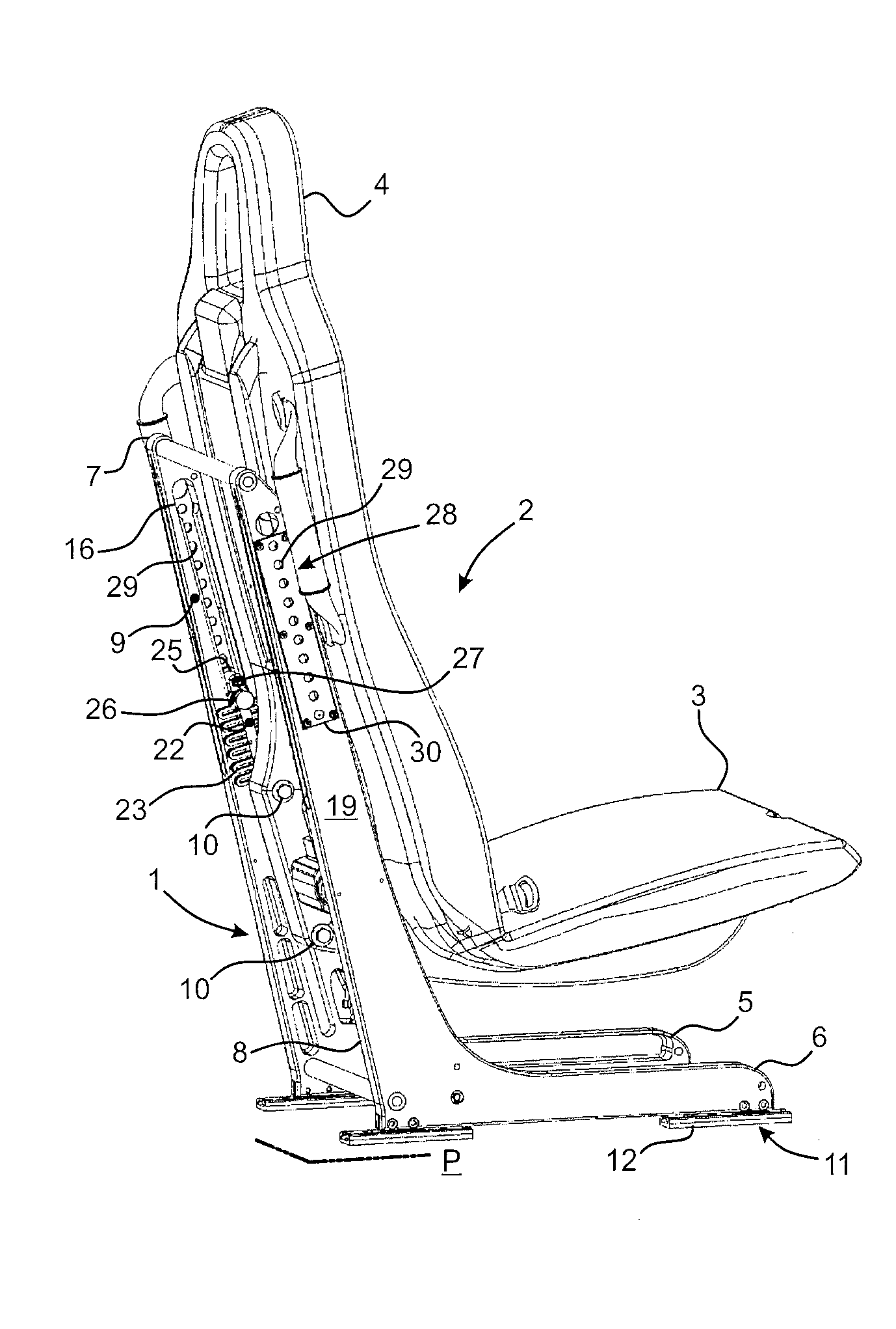
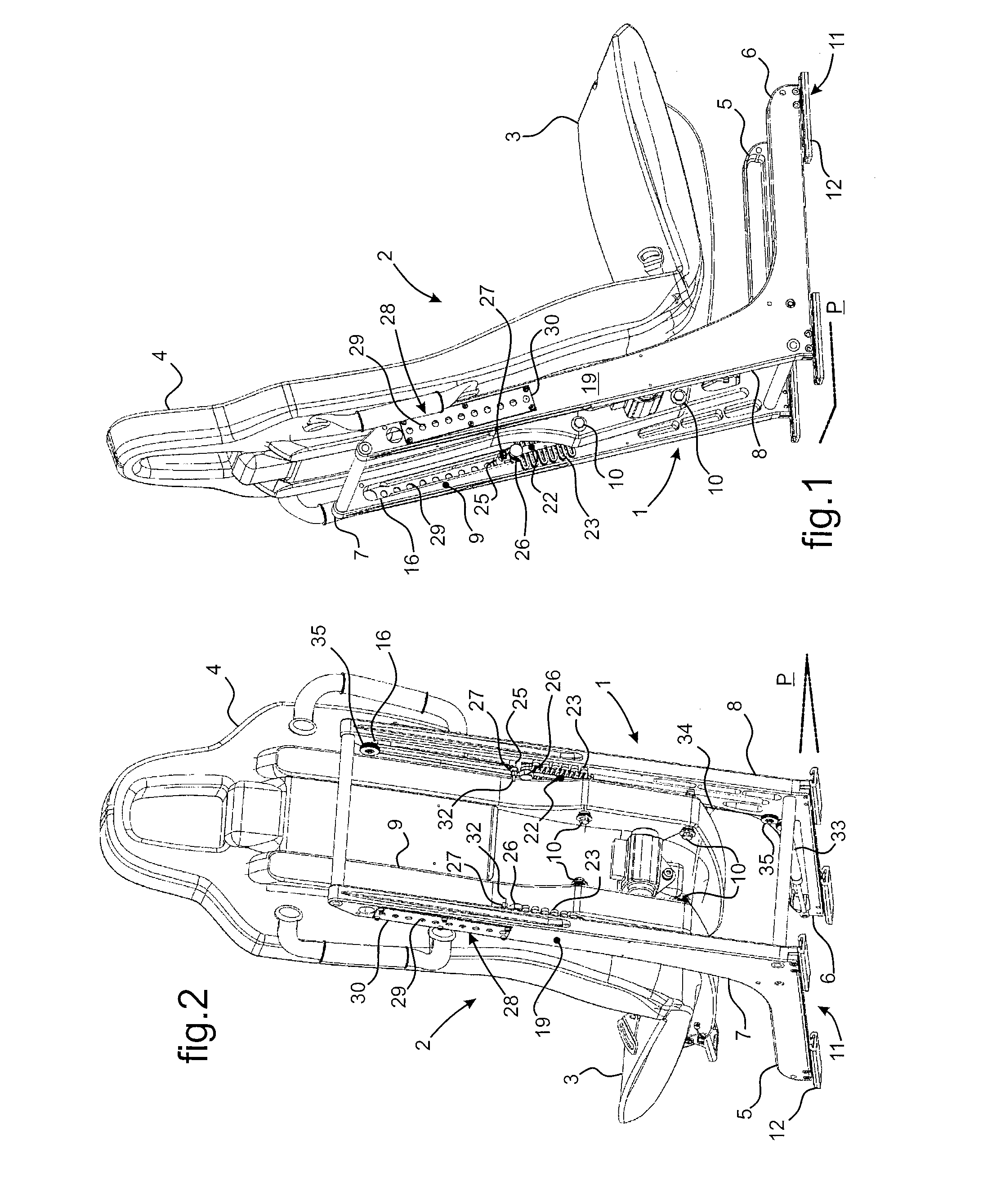
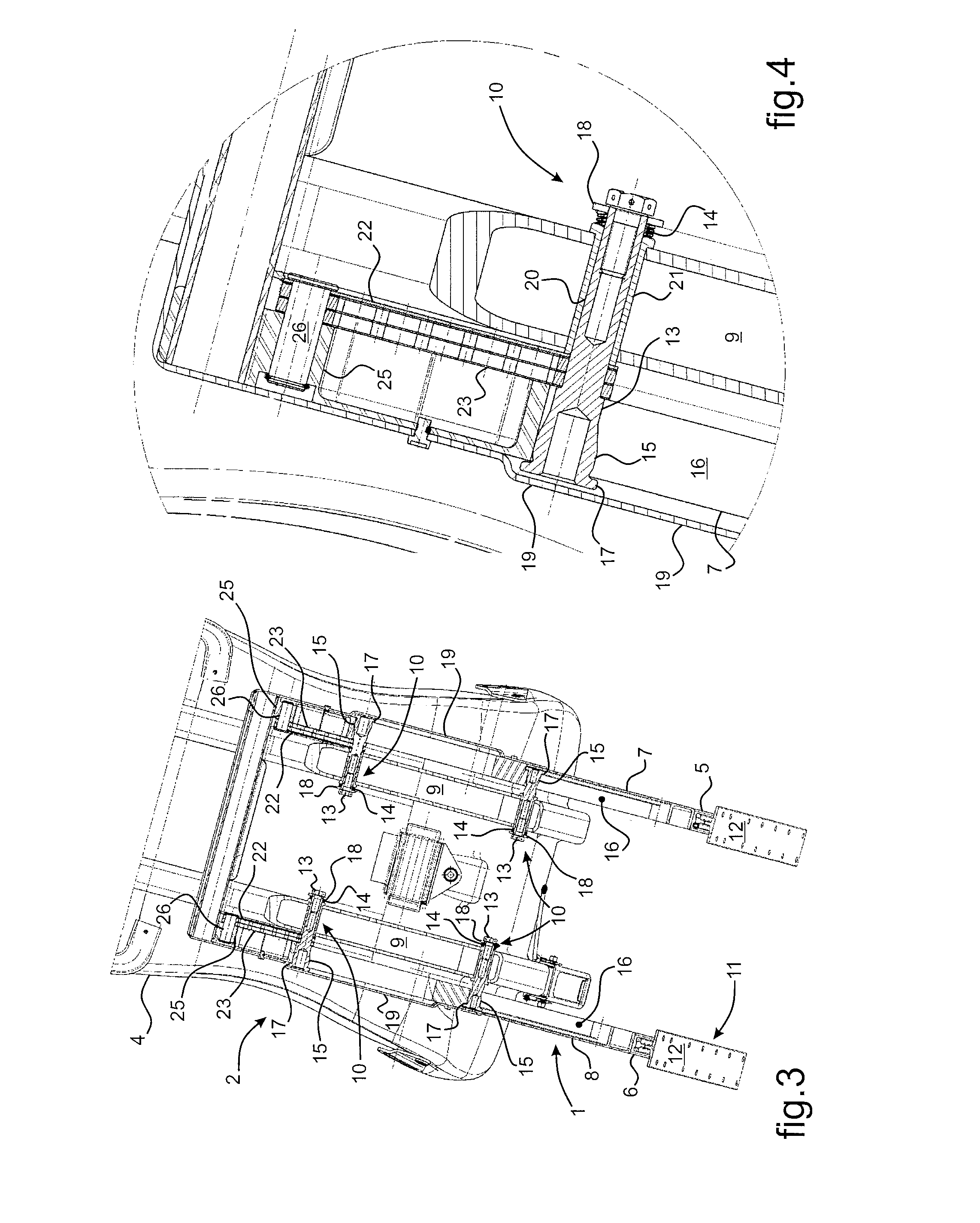
[0056]In FIGS. 1 to 3 a seat is designed for fitting to a powered aircraft, and it is arranged to protect the passenger sitting on the seat in the event of a violent impact, and more particularly in the event of the aircraft crashing. The seat is made up mainly of a stand 1 that supports in a hyperstatic manner a bucket 2 comprising a seat proper 3 and a seat back 4. The stand 1 is made up mainly of two foot members 5, 6 spaced apart laterally so as to define between them a plane P for installing the seat on the floor of the aircraft. Each of these foot members 5, 6 is extended by a respective leg member 7, 8 extending behind the seat back 4 in order to support the bucket 2. The bucket 2 is fitted with a strength member 9 made up of beams that extend under the seat 3 and behind the back 4. The beams of the strength member 9, in their zone where they are connected to the back 4, extend beside the legs 7, 8 so they can be pinned together in pairs using bolts 10. In order to ensure tha...


PUM


Abstract

A seat for a powered aircraft, the seat comprising a bucket (2) that is supported in hyperstatic manner on a stand. Leg members (7, 8) carry the bucket (2) via bolts (10). A first hinged mechanism for geometrically compensating deformation of the floor associates a ball-joint mounting of the bolts (10) on the leg members (7, 8) with an axial deformation arrangement of the bolts (10) between opposing axial bearing surfaces where they press against a strength member (9) of the bucket (2) and against the leg members (7, 8). A second energy-absorber mechanism associates fuses (22) with deformable support members (23) for the bucket (2), which members engage the bolts (10) and the leg members (7, 8) via slides (25) arranged to adjust the initial height position of the bucket (2).

Description

CROSS REFERENCE TO RELATED APPLICATION[0001]This application claims the benefit of application no. FR 09 04669 filed Sep. 30, 2009, the disclosure of which is incorporated herein by reference.FIELD OF THE INVENTION[0002]The present invention relates to the field of powered aircraft, in particular airplanes and helicopters, and more particularly it relates to the field of accessories for fitting to such aircraft. The invention provides a seat for powered aircraft, the seat incorporating means for protecting its passengers in the event of the aircraft being subjected to a violent impact and / or a sudden change of speed, in particular during a crash.BACKGROUND OF THE INVENTION[0003]The seats for powered aircraft, such as airplanes, rotorcraft, in particular helicopters, or analogous powered aircraft, incorporate means for protecting a passenger sitting on the seat in the event of a crash. The term “passenger” should be understood as covering any person on board the aircraft, whether the...

Claims


Application Information

Patent Timeline
Patent Type & Authority Patents(United States)
IPC IPC(8): B60N2/42
CPCB64D11/0619B64D11/0689
Inventor HONNORAT, OLIVIER
Owner EUROCOPTER
Why Eureka
Try Eureka