Fusion-splice fiber optic connectors and related tools

a fiber optic connector and fiber optic connector technology, applied in the field of fiber optic connectors and related tools, can solve the problems of unable to meet all assembly requirements, difficult, if not impossible, to pass all telcordia performance requirements, and bulky and difficult to route or store by the cra

Inactive Publication Date: 2013-04-02
CORNING OPTICAL COMM LLC
View PDF22 Cites 55 Cited by
  • Summary
  • Abstract
  • Description
  • Claims
  • Application Information

AI Technical Summary

Benefits of technology

[0008]In further embodiments, a cushion may be included in the splice housing for securing and protecting the fusion splice from damage or rupture. The cushion may be a tape product used in addition to or as an alternative to the heat shrink tubing noted above. In one aspect, after the tape product has been inserted in the splice housing about the fusion splice, the tape product bonds to itself to provide a protective wrap about the fusion splice. In other aspects, a glue lined heat shrink may be provided for cable jacket retention.

Problems solved by technology

Thus, the overall length of this type of fusion-splice connector is longer than other fusion-splice connectors, making it bulky and difficult to route or store by the craft.
Fusion-splice connector designs have attempted to use a standard fusion splicer and eliminate the requirement of a dedicated fusion splicer, but have encountered difficulties meeting all of the requirements for the assembly.
The added length of these fusion-splice connectors makes it difficult, if not impossible, to pass all of the Telcordia performance requirements.
For instance, optical transmission under applied load is difficult to pass, due to the added moment arm of the longer connector body.
Additionally, the extended length of this fusion-splice connector will not pass the Telcordia requirements for overall connector length.
Moreover, these fusion-spliced connectors also have a large number of parts that must be installed in the field by craft, thereby making installation cumbersome.

Method used


Image

  • Fusion-splice fiber optic connectors and related tools
  • Fusion-splice fiber optic connectors and related tools
  • Fusion-splice fiber optic connectors and related tools

Examples


Embodiment Construction

[0029]The present disclosure will now be described more fully hereinafter with reference to the accompanying drawings in which exemplary embodiments of the disclosure are shown. However, aspects of this disclosure may be embodied in many different forms and should not be construed as limited to the embodiments set forth herein. These exemplary embodiments are provided so that this disclosure will be both thorough and complete, and will fully convey the scope of the disclosure to those skilled in the art. Whenever possible, like reference numerals will be used throughout the detailed description of the disclosure to refer to like or similar elements of the various drawings.

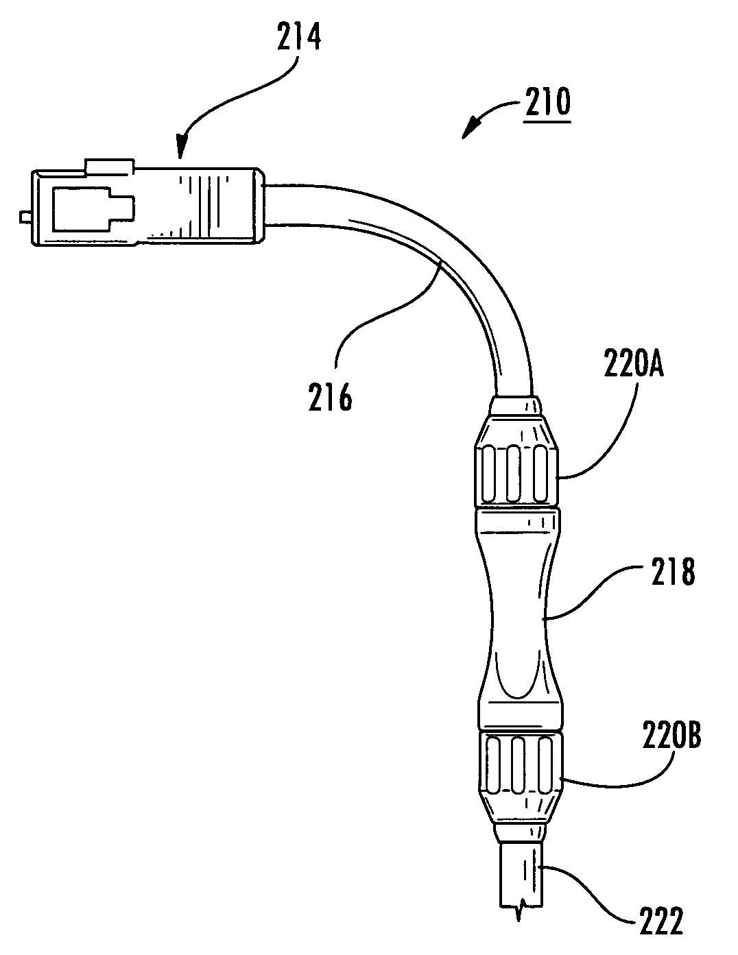
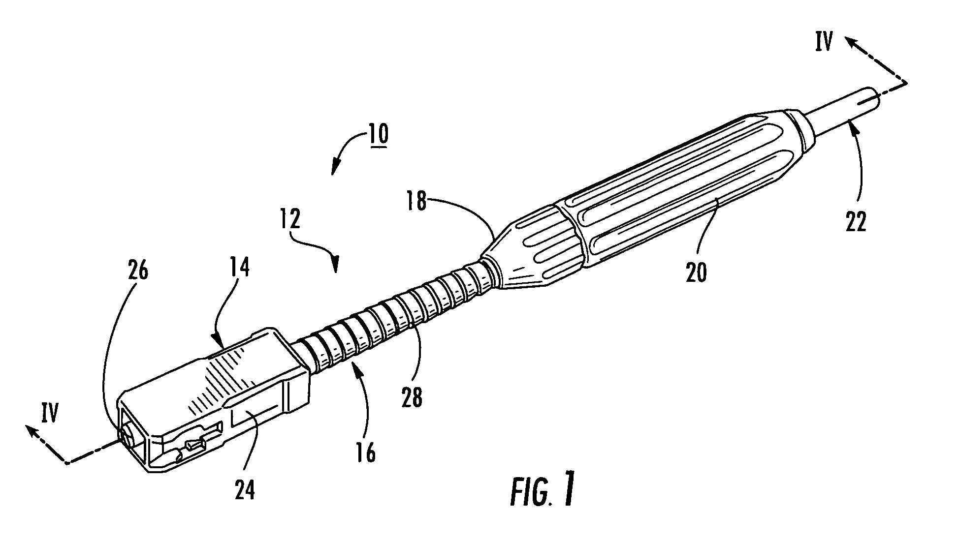
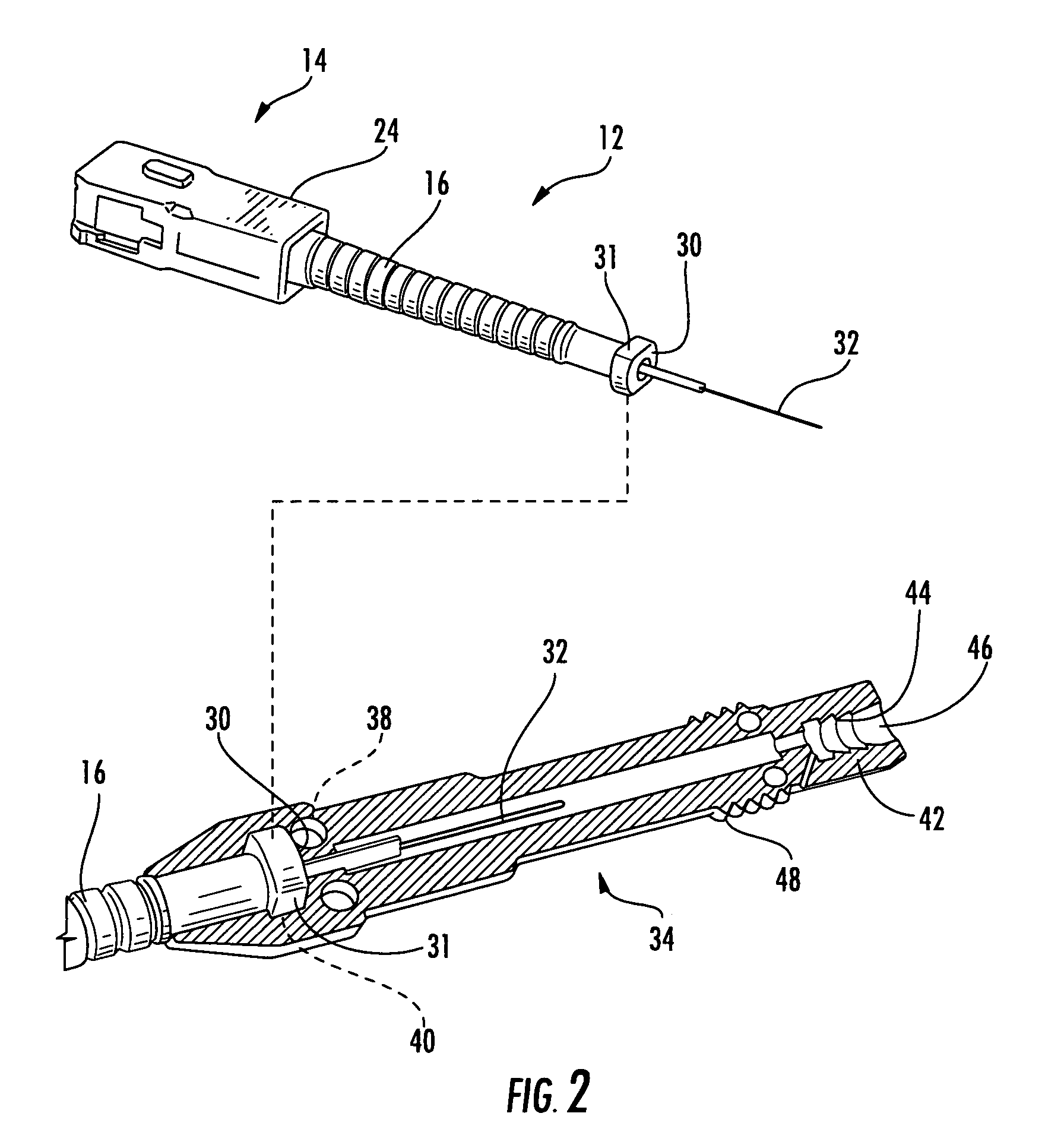
[0030]The present disclosure generally provides various embodiments of a fiber optic connector assembly suitable for fusion splicing. The various embodiments are made from lightweight, economical materials and components that are simple to manufacture and are easily used in the field by a technician.

[0031]With refe...


PUM


Abstract

Fiber optic connectors having an optical fiber stub that is fusion-spliced for optical connection and related tools for the fiber optic connectors are disclosed. Specifically, the connector assembly for fusion-splicing includes a fiber optic connector having an optic fiber stub and a boot attachable to the fiber optic connector. The boot is configured to transfer the majority of the axial force from the fiber optic cable to the fiber optic connector. Specifically, a splice housing for housing the fusion splice is configured for attachment to an end of the boot for transferring forces from the fiber optic cable to the boot. Consequently, the boot preferably has an extensibility of less than about 2 millimeters under an axial load of about fifteen pounds to inhibit excess forces from acting on the optical fiber stub.

Description

CROSS REFERENCE TO RELATED APPLICATIONS[0001]This application claims benefit of U.S. Provisional Application Ser. No. 60 / 959,702, filed Jul. 16, 2007.FIELD OF THE DISCLOSURE[0002]The present disclosure relates to fiber optic connectors and related tools. More specifically, the present disclosure relates generally to fiber optic connectors having an optical fiber stub suitable for fusion-splicing for optical connection and related tools for the fiber optic connectors.BACKGROUND OF THE DISCLOSURE[0003]Field installable fusion-splice connectors that require dedicated fusion splicers for installation have been developed. One type of fusion splicer is designed for a fusion-splice connector using a stub optical fiber in an extended length ferrule. The extended length ferrule has a notch or hole cut near the middle where the fusion splice is made. The stub optical fiber ends at the notch or hole and the field fiber is inserted into the opposite end of the ferrule for fusion splicing with t...

Claims


Application Information

Patent Timeline
Patent Type & Authority Patents(United States)
IPC IPC(8): G02B6/38
CPCG02B6/3846G02B6/2551G02B6/2558G02B6/3887G02B6/3889G02B6/3888G02B6/38875
Inventor DE JONG, MICHAELLEYVA, JR., DANIELYOW, JR., CHARLES A.
Owner CORNING OPTICAL COMM LLC
Why Eureka
Try Eureka