
Electrical generators for low-frequency and time-varying rocking and rotary motions

a generator and low-frequency technology, applied in the field of electric generators, can solve the problems of increasing equipment cost, significant down time, maintenance and service cost, etc., and achieve the effects of low maintenance cost, simple operation, and minimal service and maintenan

Active Publication Date: 2013-04-02
OMNITEK PARTNERS LLC
View PDF15 Cites 16 Cited by
  • Summary
  • Abstract
  • Description
  • Claims
  • Application Information

AI Technical Summary

Benefits of technology

[0008]There is therefore a need for a method that can be used to develop electrical energy generators that could efficiently generate electrical energy from slow and time varying rocking (oscillatory) platforms and rotary input motion. To achieve high mechanical energy to electrical energy conversion efficiency, the above method can lead to generators that operate at high and relatively constant input motion frequencies.
[0010]There is also a particular need for efficient electrical energy generators for rotary machinery, such as windmills and / or turbines, used to harvest tidal or ocean waves or other similar flows and the like in which the input motion varies widely and could even reverse, with input rotational velocities that could be very low, even of the order of 5-10 round per minute (rpm) or even lower. In particular, there is a need for such electrical energy generators to operate without the need for costly speed increasing and regulating devices that significantly increase the equipment cost as well as maintenance and service costs and result in significant amount of down time.
[0011]Accordingly, a method is provided for electrical energy generators to harvest electrical energy, i.e., convert mechanical energy to electrical energy, from slow and time varying rocking (oscillatory) platforms and rotary input motion. With this method, the generator device does not require devices such as speed increasing devices and / or speed regulating devices. In addition, the disclosed method can provide the means to develop highly efficient mechanical energy to electrical energy conversion devices since the resulting mechanical to electrical energy conversion devices can operate at appropriately high and relatively constant input motion frequencies.
[0016]The electrical energy generators can be very simple, can efficiently operate over a very large range of input oscillatory frequencies or rotary speeds, and can require minimal service and maintenance.

Problems solved by technology

In particular, there is a need for such electrical energy generators to operate without the need for costly speed increasing and regulating devices that significantly increase the equipment cost as well as maintenance and service costs and result in significant amount of down time.

Method used


Image

  • Electrical generators for low-frequency and time-varying rocking and rotary motions
  • Electrical generators for low-frequency and time-varying rocking and rotary motions
  • Electrical generators for low-frequency and time-varying rocking and rotary motions

Examples


embodiment 30

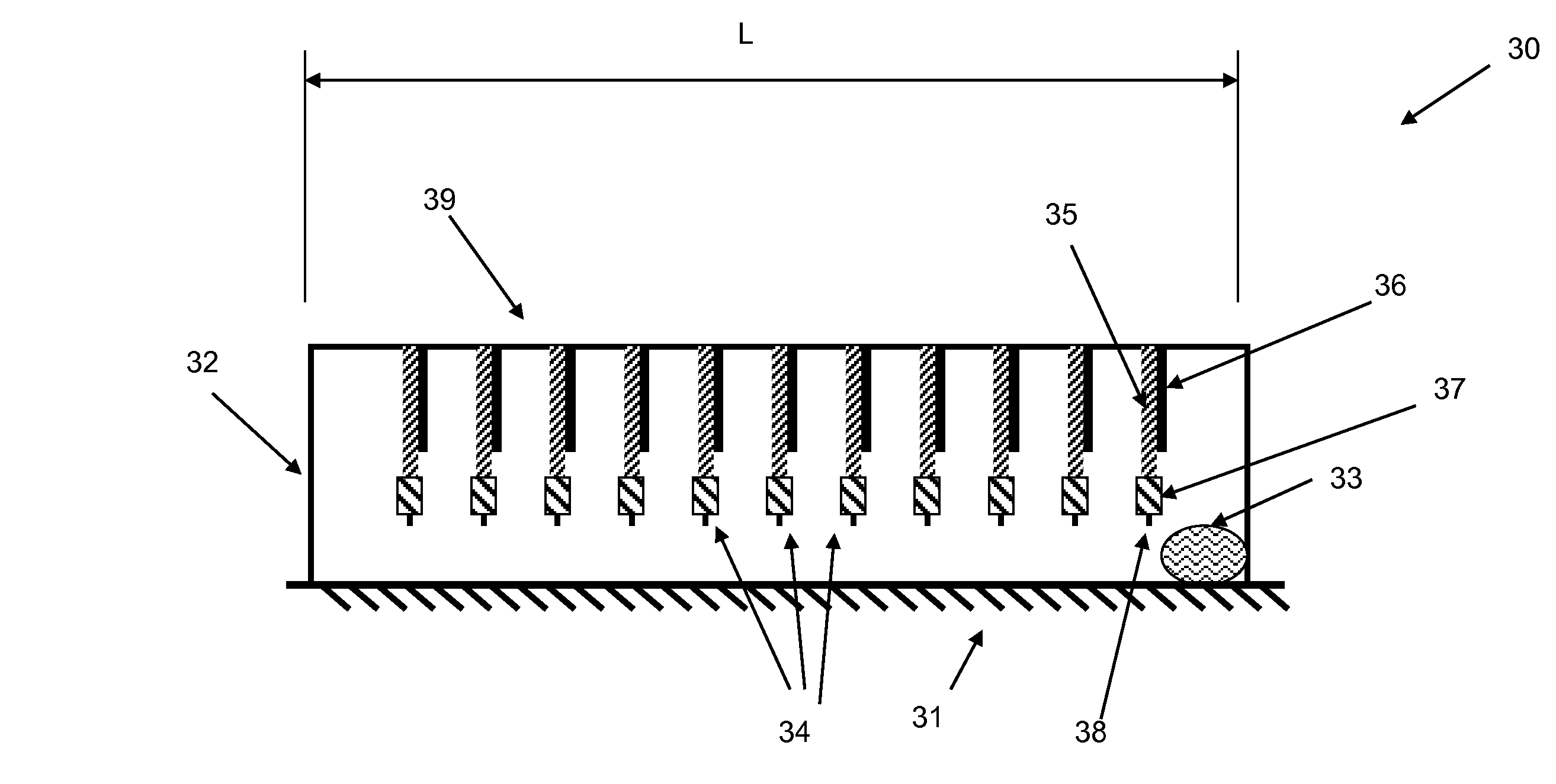
[0043]The above novel two-stage energy harvesting method for rocking platforms is best described by the following basic embodiment 30, which is shown schematically in FIG. 3. The primary system of the embodiment 30 consists of a simple housing 32, which is attached directly to the rocking platform 31. The rocking oscillation of the platform 31 is considered to be about an axis perpendicular to the plane of the page. As the platform 31 undergoes rotary oscillation, the traveling mass 33 begins to slide from the side that has been raised, travels the length of the housing 32 and ends on its opposite end of the housing. At least one secondary vibratory element 34 is attached to the top portion 39 of the housing 32. Each vibratory element consists of a relatively flexible beam 35, to the tip of which is preferably attached a mass 37 to allow for optimal tuning of the natural frequency of the first mode of vibration of the vibratory elements. The tip of the beam 35 and mass 37 assemblies...

embodiment 50

[0057]The schematic of a basic embodiment 50 of such a two-stage generator design for harvesting energy from slow and varying rotary motion is shown in FIG. 5. The generator consists of an outer housing 51, which is fixed, for example to a fixed structure 52. Internal to the housing is mounted at least one and preferably more secondary vibrating elements 55. In the schematic of FIG. 5, the secondary vibrating elements 55 are constructed as vibrating beam elements 56, over the surface of which certain active materials based mechanical to electrical energy transforming elements 57, such as bimorph piezoelectric elements, are mounted. The input is the rotating (or oscillating) shaft 53, to which at least one exciter tooth 54 is mounted. The shaft 53 is shown without bearing and support elements known in the art for the sake of clarity. The generator can operate as follows.

[0058]As the input shaft 53 rotates or oscillates rotationally, the exciter teeth 54 engage the tip 58 of the secon...

embodiment 120

[0075]It is appreciated by those skilled in the art that the flexible beam 121 of the embodiment 120 of FIG. 12 itself may be constructed fully or partially with piezoelectric materials for the purpose of converting mechanical energy of rotational vibration of the secondary vibratory system 120 can be converted into electrical energy. In addition, the effective spring rate of the flexible beam elements 121 may be designed to correspond to the desired spring rate of the torsion spring element 104, thereby eliminating the need for the torsion spring element 104.


PUM


Abstract

An apparatus for generating electrical energy from a first motion having a low and / or variable frequency. The apparatus including: a first device to which the first motion is transferred; and a second device to which the first motion is transferred from the first device, the second device operating at a second motion having a frequency which is higher and / or more constant that the first motion. Wherein the first device comprises one of a first rotating shaft or first translating mass; the first shaft or first mass includes a tip interacting with the second device to transfer the first motion thereto, the second device comprises a mechanism having an electrical energy generator for converting the second motion to electrical energy; and the electrical energy generator comprises a rotary or linear coil and magnet generator or a piezoelectric generator. The interaction of the tip with the shaft or mass can be contactless.

Description

CROSS-REFERENCE TO RELATED APPLICATION[0001]This application is a Continuation-In-Part of U.S. application Ser. No. 12 / 142,739 filed on Jun. 19, 2008, the contents of which is incorporated herein by reference.BACKGROUND OF THE INVENTION[0002]1. Field of the Invention[0003]The present invention relates generally to electrical generators, and more particularly to electrical generators for low-frequency and time-varying rocking and rotary motions.[0004]2. Prior Art[0005]In recent years, particularly following the development of low-power electronics, sensors and wireless communications devices, electrical energy generators that harvest energy from the environment have seen renewed attention. The most common means of generating electrical energy is the use of magnets and coils using rotary type of generators. Generators that harvest energy from vibration that use either coils and magnets or active materials such as piezoelectric materials based devices have also been developed, particul...

Claims


Application Information

Patent Timeline
Patent Type & Authority Patents(United States)
IPC IPC(8): H01L41/113
CPCF03G7/08H01L41/1134H01L41/1136H02K7/1876H02K7/1892H02N2/18H10N30/304H10N30/306
Inventor RASTEGAR, JAHANGIR S.SPINELLI, THOMASMURRAY, RICHARD T.
Owner OMNITEK PARTNERS LLC
Learn More