Methods and systems for identifying hazardous flight zone areas on a display

a technology for hazardous flight zones and displays, applied in the field of methods and systems for identifying hazardous flight zone areas on displays, can solve problems such as computational intensive algorithms and overly complicated shapes

Active Publication Date: 2013-04-02
HONEYWELL INT INC
View PDF29 Cites 4 Cited by
  • Summary
  • Abstract
  • Description
  • Claims
  • Application Information

AI Technical Summary

Benefits of technology

[0019]The advantage of the present invention is that it is very fast and requires a consistent amount of processing time. The shapes are stored effectively in a two-dimensional array. In one embodiment, the data for the shapes is collected from a couple sources (e.g., turbulence data or VIR data) which are then processed into a 2D buffer. Therefore every point is either part of the shape or not. The center of mass can be determined simply by adding the X's and Y's of every point in the object and dividing by the number of points in the object.

Problems solved by technology

A second option is to draw an outline around the area, but that can make an overly complicated shape that may be constantly changing shape as the airplane or weather changes over time.
These comparisons along with the recursion make this a very computational intensive algorithm.

Method used


Image

  • Methods and systems for identifying hazardous flight zone areas on a display
  • Methods and systems for identifying hazardous flight zone areas on a display
  • Methods and systems for identifying hazardous flight zone areas on a display

Examples


Embodiment Construction

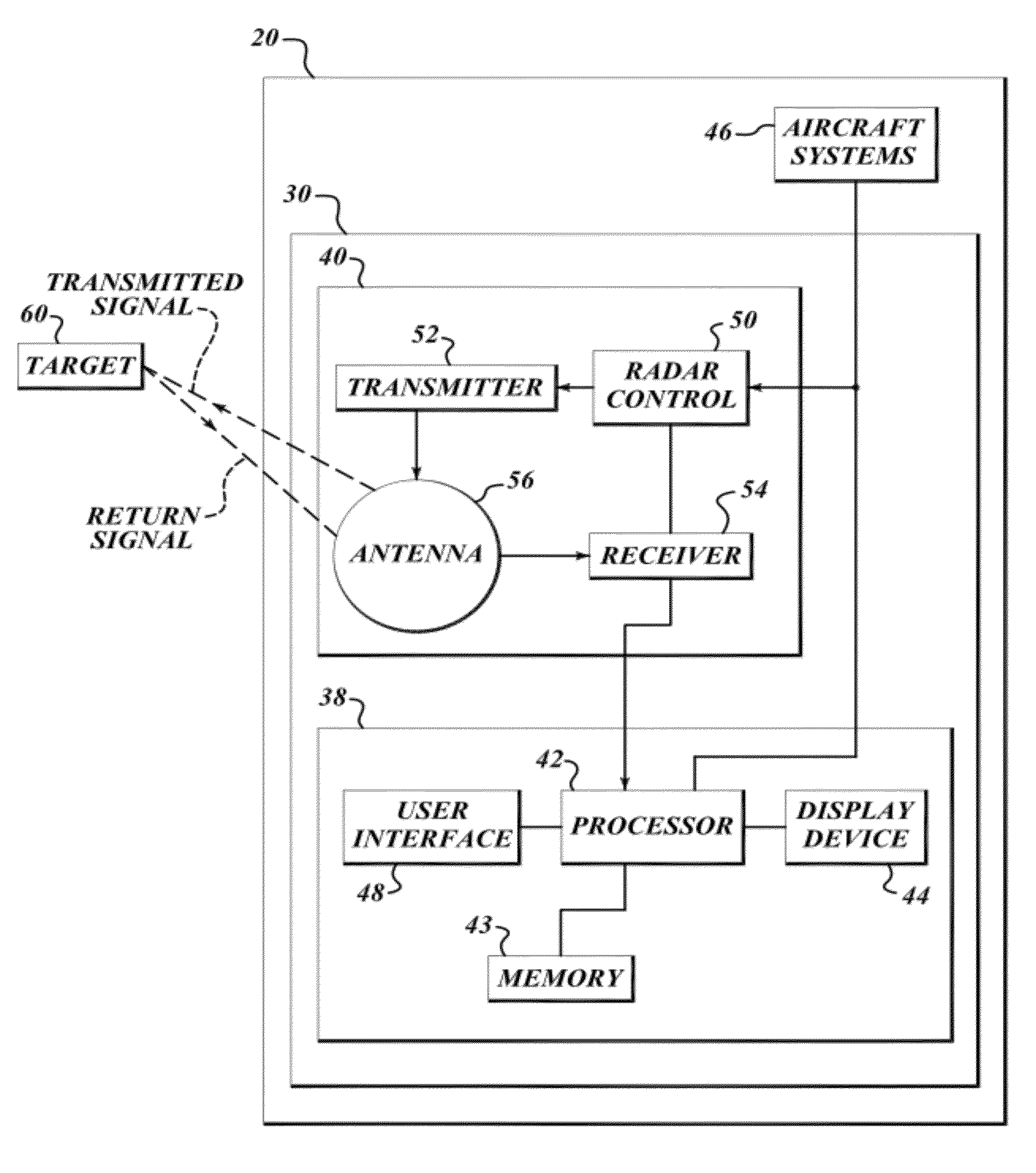
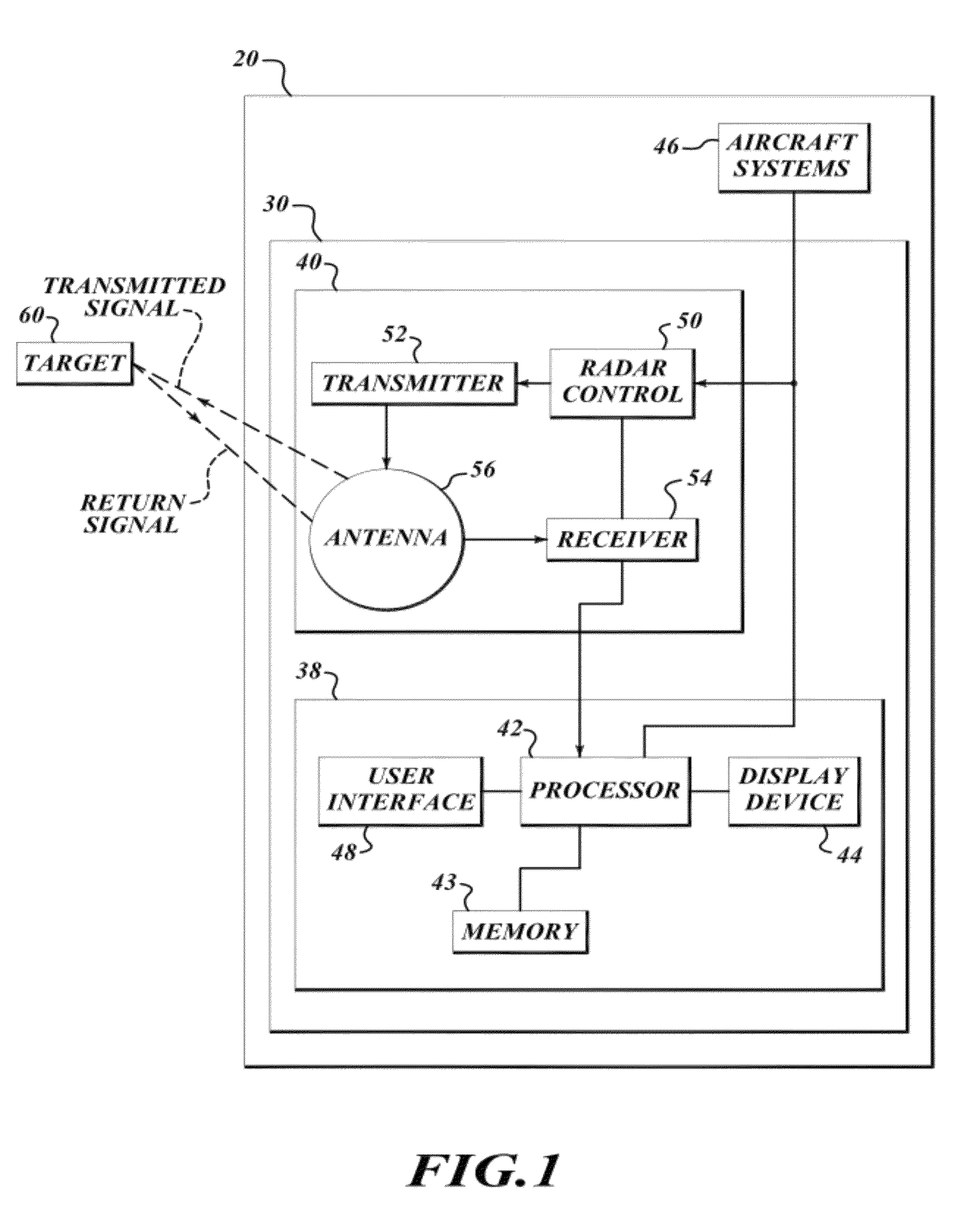
[0012]FIG. 1 illustrates an example system 30 implemented on an aircraft 20 for providing more accurate flight plan / path weather information. The system 30 includes a weather radar system 40 and a radar display system 38 that includes a display processor 42, memory 43, a display device 44, and a user interface device 48. The aircraft 20 also includes other aircraft systems 46, such as an air data computer (ADC), that are in signal communication with the weather radar system 40 and the radar display system 38. The display processor 42 is electrically coupled to the radar system 40, the display device 44, the other aircraft systems 46, the user interface device 48 and the memory 43. The radar system 40 includes a radar controller 50, a transmitter 52, a receiver 54 and an antenna 56. The radar controller 50 controls the transmitter 52 and the receiver 54 for performing the transmitting and receiving of signals through the antenna 56 based on the selected radar mode and other pilot inp...


PUM


Abstract

Systems and methods for representing a weather hazard without also including a large percentage of non-hazard area. An exemplary system includes a memory that stores radar reflectivity data in a three-dimensional buffer, a display device and a processor that is in data communication with the memory and the display device. The processor receives a two-dimensional shape based on a portion of the data stored in the three-dimensional buffer, then finds a center of the shape. Next the processor finds the furthest away point of the shape in a plurality of regions sharing the center as a common point and generates a polygon based on the furthest away points. The display device displays the generated polygon. The shape is associated with hazardous weather information determined from the radar reflectivity data stored in the three-dimensional buffer. The display device is an aircraft weather radar display.

Description

BACKGROUND OF THE INVENTION[0001]Weather radar system algorithms were developed to determine hazardous flight zone areas. One solution for indicating a hazardous area to the pilot was to surround the area in question with a series of connected lines. One option is a simple box that surrounds the hazardous area, but it may include a lot of area that is not hazardous and therefore would be safe to fly in. A second option is to draw an outline around the area, but that can make an overly complicated shape that may be constantly changing shape as the airplane or weather changes over time.[0002]Another technique uses simplified polygons. Current simplified polygon techniques suggest a recursive tracing algorithm. The first step is to trace the outline of the object. Then a recursive algorithm checks each outline point with other points on the outline to see if a new line can be added that creates a simplified outline. This requires running an algorithm to compute a value for each line to...

Claims


Application Information

Patent Timeline
Patent Type & Authority Patents(United States)
IPC IPC(8): G01S7/04G01S13/95
CPCG06T7/0083G06T2207/30181G06T2207/20168G06T2207/10032G06T7/12
Inventor ROWEN, RODNEY A.BUNCH, BRIAN P.
Owner HONEYWELL INT INC
Why Eureka
Try Eureka