
Liquid crystal display with a reduced flexoelectric effect

a liquid crystal display and flexoelectric technology, applied in non-linear optics, instruments, optics, etc., can solve the problems of increased material cost, complicated electrode configuration in each pixel, and image quality decline, and achieve the effect of reducing the flexoelectric effect of the liquid crystal display

Active Publication Date: 2013-04-02
JAPAN DISPLAY WEST
View PDF17 Cites 3 Cited by
  • Summary
  • Abstract
  • Description
  • Claims
  • Application Information

AI Technical Summary

Benefits of technology

This patent describes a liquid crystal display with a light shield that prevents unwanted light from affecting the display quality. The shield is placed to overlap the outermost strip of each pixel electrode or the entire electrode. The display also includes a dummy electrode to reduce the flexoelectric effect, which causes polarization and affects the display quality. Additionally, narrowing the inter-pixel region and reducing the flexoelectric effect can prevent screen flickering and improve image quality. These measures achieve high image quality with a simple configuration.

Problems solved by technology

Accordingly, luminance of the liquid crystal display varies from frame to frame, and flickers occur on a screen to cause a decline in image quality.
However, in the liquid crystal display disclosed in Japanese Patent No. 3668844, the electrode configuration in each pixel is complicated.
In the liquid crystal display disclosed in Japanese Unexamined Patent Application Publication No. 2009-167228, because the molecular structure of the liquid crystal is complicated, material cost may increase, or the viscosity or birefringence of the liquid crystal may decrease.
Further, in the case where various specifications are to be met, it is necessary to make a molecular design such as to obtain a molecular structure satisfying the specifications, and development cost may be expensive.

Method used


Image

  • Liquid crystal display with a reduced flexoelectric effect
  • Liquid crystal display with a reduced flexoelectric effect
  • Liquid crystal display with a reduced flexoelectric effect

Examples


first embodiment

[0057]1. First Embodiment

[0058]a. Configuration Example

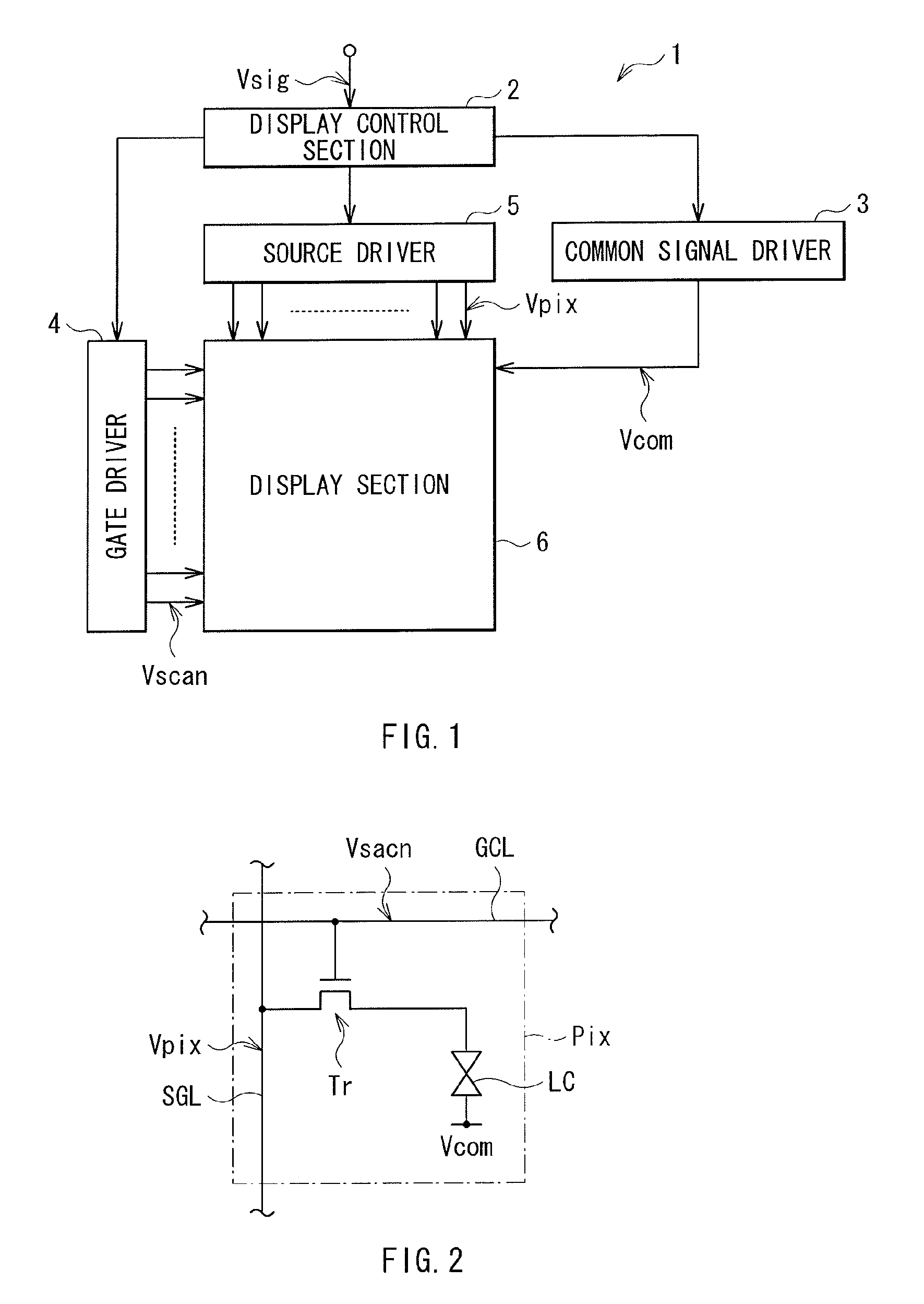
[0059]FIG. 1 illustrates an example of a liquid crystal display according to a first embodiment. A liquid crystal display 1 is an FFS mode liquid crystal display which prevents light from passing through a part of a pixel electrode corresponding to a part prone to cause a flexoelectric effect. The liquid crystal display 1 includes a display control section 2, a common signal driver 3, a gate driver 4 and a source driver 5.

[0060]The display control section 2 stores and maintains a supplied image signal Vsig for each screen (for display of each frame) in a frame memory configured of an SRAM (Static Random Access Memory) or the like. Moreover, the display control section 2 has a function of controlling the common signal driver 3, the gate driver 4 and the source driver 5 which drive a display section 6 to operate in conjunction with one another. More specifically, the display control section 2 supplies a common signal timing contro...

second embodiment

[0110]2. Second Embodiment

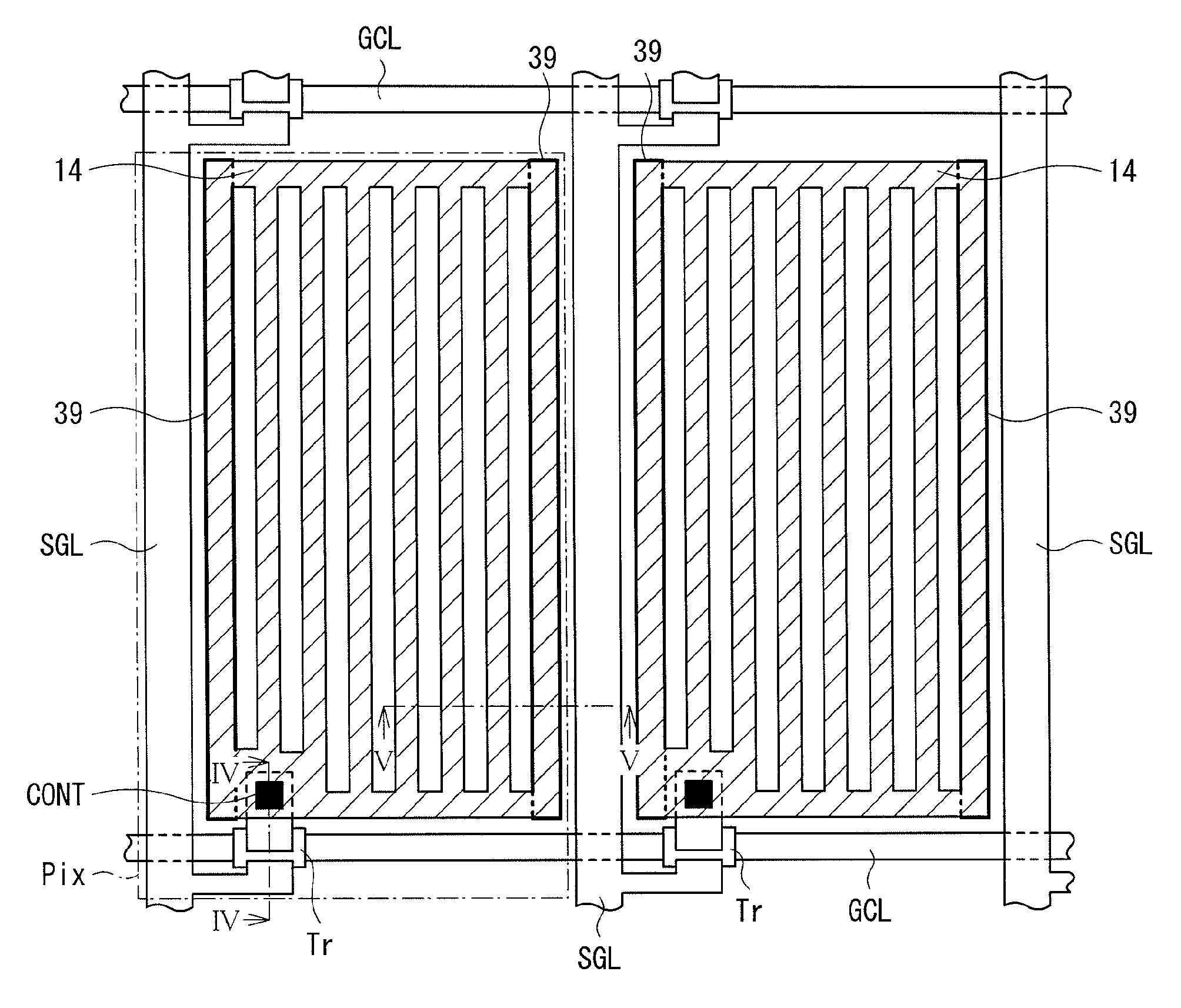
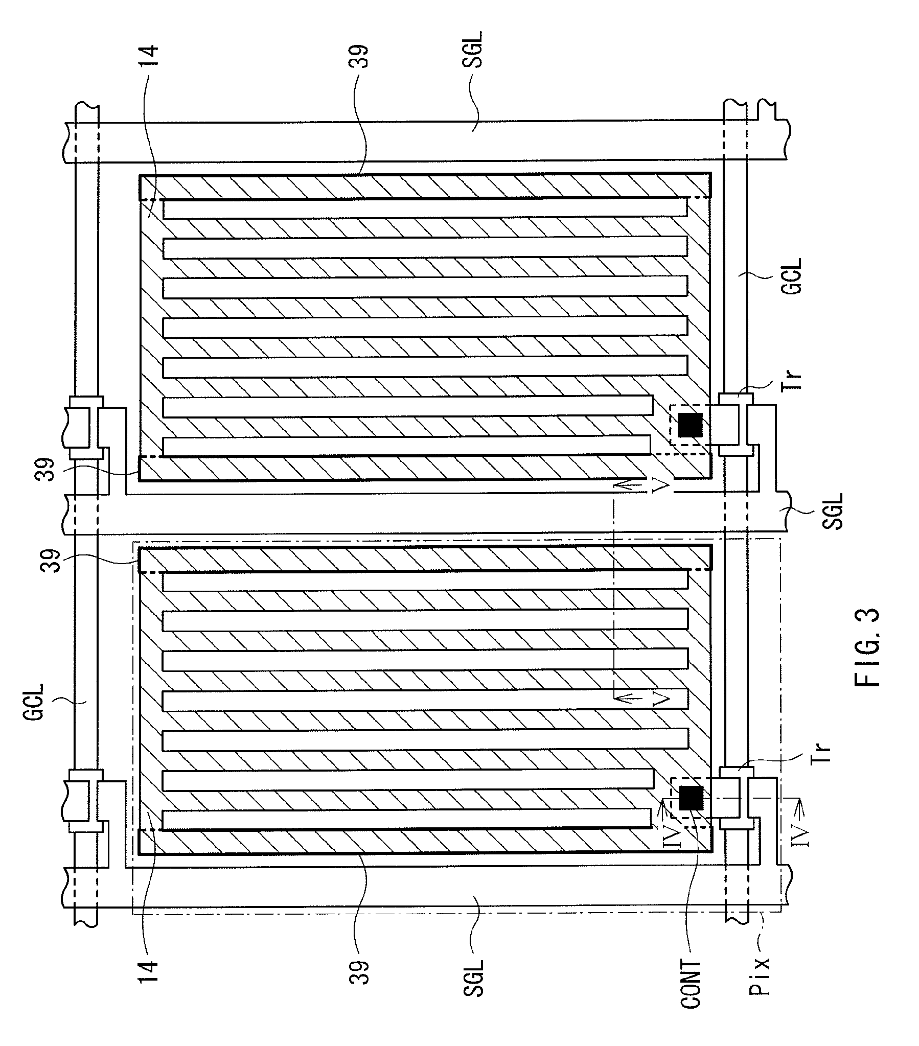
[0111]Next, a liquid crystal display according to a second embodiment will be described below. In the second embodiment, the position of the light shield in a pixel is different from that in the first embodiment. In other words, in the first embodiment (refer to FIG. 3), the light shield is arranged in a region corresponding to the outermost strip of the pixel electrode, but in the present embodiment, the light shield is also arranged in a region between the pixel electrodes of adjacent pixels. Other configurations are the same as those in the first embodiment (refer to FIGS. 1 and 3). Note that like components are denoted by like numerals as of the liquid crystal display according to the first embodiment and will not be further described.

[0112]FIG. 14 illustrates an example of a display section 51 according to the second embodiment, and FIG. 15 illustrates a sectional view taken along an arrow direction XV-XV of the display section 51 illustrated in FIG. 1...

third embodiment

[0116]3. Third Embodiment

[0117]Next, a liquid crystal display according to a third embodiment of the invention will be described below. In the third embodiment, the pixel signal line doubles as a light shield. Other configurations are the same as those in the first embodiment (refer to FIGS. 1 and 3). Note that like components are denoted by like numerals as of the liquid crystal display according to the first embodiment and will not be further described.

[0118]FIG. 16 illustrates a configuration example of a display section 54 according to the third embodiment, and FIG. 17 illustrates a sectional view taken along an arrow direction XVII-XVII of the display section 54 illustrated in FIG. 16. The display section 54 includes a pixel signal line SGL2. The pixel signal line SGL2 has a large width along the first direction, and overlaps outermost strips of the pixel electrodes 14 of pixels Pix adjacent to the pixel signal line SGL2 on both sides.

[0119]The pixel signal line SGL2 correspond...


PUM

PropertyMeasurementUnit
electric fieldaaaaaaaaaa
poweraaaaaaaaaa
dipole momentaaaaaaaaaa

Abstract

A liquid crystal display with a first substrate and a first pixel electrode on the first substrate. The first pixel electrode extends along first and second directions and has a plurality of first pixel electrode strips arranged along a first direction. The display also has a common electrode on the first substrate that is spaced from the pixel electrode along a third direction. In addition, the display has a light shield extending along the second direction and positioned to overlap at least part of an outermost strip of the first pixel electrode along the first direction.

Description

CROSS REFERENCES TO RELATED APPLICATIONS[0001]This application claims priority to Japanese Patent Application JP 2010-029009 filed in the Japanese Patent Office on Feb. 12, 2010 and Japanese Patent Application JP 2010-031434 filed in the Japanese Patent Office on Feb. 16, 2010, the entire contents of both being incorporated herein by reference to the extent permitted by law.BACKGROUND OF THE INVENTION[0002]The present invention relates to a liquid crystal display driven by a lateral electric field drive mode and an electronic unit including the liquid crystal display.[0003]In recent years, due to their low power consumption, space saving or the like, liquid crystal displays have become e mainstream displays. One of liquid crystal drive modes is a lateral electric field drive mode, such as an FFS (Fringe Field Switching) mode or an IPS (In-Plane Switching) mode. The lateral electric field drive mode is a drive mode for achieving display by forming an electric field in a direction par...

Claims


Application Information

Patent Timeline
Patent Type & Authority Patents(United States)
IPC IPC(8): G02F1/1335G02F1/1343
CPCG02F1/134363G02F1/133512G02F1/133514G02F1/133784G02F1/1368G02F1/134372
Inventor TSURUMA, TAKEYUKITANAKA, HIRONAOWATANABE, MAKOTOYAMAGUCHI, HIDEMASAHIGASHI, AMANEITO, YOUBUNGOTO, YUSUKE
Owner JAPAN DISPLAY WEST
Learn More