Communication cable connection box with waterproof device of elastic rubber shrinking pipe

a technology of elastic rubber and shrinkable tubes, which is applied in the field of communication cable splice boxes, can solve the problems of water leakage problems in splice boxes, the inability of flexible rubber shrinkable tubes the inability to carry out effective waterproofing treatment between the grooves of two cables, etc., and achieves the effect of reducing the risk of splicing, bending and/or loosening of cables

Active Publication Date: 2013-04-02
KOREA AEROSPACE INDUSTRIES
View PDF8 Cites 3 Cited by
  • Summary
  • Abstract
  • Description
  • Claims
  • Application Information

AI Technical Summary

Benefits of technology

[0009]Shrinkable tubes are hollow cylindrical composite rubber tubes that are highly flexible and ductile, and the walls of hollow cylindrical rubber tubes are first covered with fireproof hard plastic strips that are coiled into a screw like tube. The hollow diameter of the stretched shrinkable rubber tube is wider than that of the hollow cylindrical tube and the outer diameter of cable which will penetrate the hollow cylindrical tuber diameter. When the plastic strip is extracted, the stretched hollow diameter immediately shrinks elastically, returning to the smaller diameter prior to being stretched, and the smaller diameter is smaller than the hollow cylindrical tube and the outer diameter of the cable which penetrates the hollow cylindrical tube. This results in the exterior of the hollow cylindrical tube and a portion of the cable that has not penetrated the hollow cylindrical tube to be tightly wrapped around each other, forming a waterproof structure. This waterproof structure can solve the technical problems caused by torching to waterproof the access openings for cables in heat-shrink cable splice box. When torching other heat-shrink tubes for cable openings, it often results in heat-shrink tubes that are already completed to be subjected to further torching, causing them to soften, loosen and resulting in water leakage problems in splice boxes. Since the current invention utilizes simple and safe construction, without the need for tools or a fire source, with a wider applicable outer diameter of cable along with other advantages, it can significantly reduce the cost of investing enterprises.
[0013]The second reason stated above, often as a result of completing the heat-shrink waterproofing of a splice box, due to shifting the cable box into / out of the hand-hole or manhole to carry out cable rerouting, threading out divided cable, maintenance and such activities, cables are prone to being twisted, bent / or under pressure, causing the waterproof treatment section of heat-shrink tube to loosen, resulting in water leakage in splice boxes. In general, most cables are multi-coated with polyethylene. However, adhesion strength is limited between the thermal adhesive that coats the cable of the heat-shrink tube's interior, and the multi-coated polyethylene cable, thus resulting in the ease of cables twisting, bending and / or loosen under pressure.

Problems solved by technology

When torching other heat-shrink tubes for cable openings, it often results in heat-shrink tubes that are already completed to be subjected to further torching, causing them to soften, loosen and resulting in water leakage problems in splice boxes.
Therefore, while carrying out branch splicing operation of the backbone cable, unless using a suitable way to modify the cross-section of the two cables of the main cable responsible for mid-span connecting splicing into a rounded, oval or a groove-less polygonal shape, the flexible rubber shrinkable tube cannot carry out an effective waterproofing treatment between the grooves of two cables.
When torching other heat-shrink tubes for cable openings, it often results in heat-shrink tubes that are already completed to be subjected to further torching, causing them to soften, loosen and resulting in water leakage problems in splice boxes.

Method used


Image

  • Communication cable connection box with waterproof device of elastic rubber shrinking pipe
  • Communication cable connection box with waterproof device of elastic rubber shrinking pipe
  • Communication cable connection box with waterproof device of elastic rubber shrinking pipe

Examples


embodiment 1

[0027]Please refer to FIG. 3(A), which is a diagram showing a flexible rubber shrinkable tube used in Embodiment 1 of the present invention. In FIG. 3(A), the flexible rubber shrinkable tube 40 (abbreviated as shrinkable tube) is constructed by the flexible and ductile ethylene propylene rubber (EPR) tube 41 (hereinafter abbreviated as “rubber tube”) and a rigid polyethylene plastic strip 42 (hereinafter abbreviated as “plastic strip”), of which rubber tube 41 having a first opening 411 and a second opening 412, and plastic strip 42 has a first end 421 and a second end 422. The rubber strip 42 is first coiled in a spiral pattern within the inner wall of the hollow rubber tube 41, the hollow diameter of rubber tube 41 is stretched by plastic strip 42, while the hollow diameter of the stretched rubber tube 41 is greater than the outer diameter of the hollow cylindrical tube of the cable splice box, and also the outer diameter of the cable. Plastic strip 42 is ultrasonically welded for...

embodiment 2

[0030]Please refer to FIG. 4, which is a diagram of the communication cable splice box with a shrinkable rubber tube device that is flexible and waterproof, shown in Embodiment 2 of the present invention. In FIG. 4, communication cable splice box 60 (abbreviated as “splice box” thereafter) at least is constructed of cables entry board 61, protective cover 62 (partially), hollow cylindrical tubes 63, 64, 65, flexible rubber shrinkable tube 70, heat-shrink tube 73 and manifold clip 74 used for heat-shrink tube. Splice box 60 can supply straight direct splicing, mid-span splicing and branch splicing operation of the backbone cable, three different types and forms of splicing. According to FIGS. 2(A), 2(B) and “Background of the invention” part, the main cables 68, 69 penetrate hollow cylindrical tube 64 which is wrapped with heat-shrink tube 73, the manifold clip 74 used for heat-shrink tube is used to clip the seams between main cables 68, 69, and then heat-shrink tube 73 and manifold...

embodiment 3

[0032]The waterproof treatment of Embodiments 1 and 2 of the present invention can effectively solve the water-leakage problems in splice boxes. Furthermore, the user can secure the cable entering the splice box with a cable fixture device secured on the exterior of the splice box, strengthening the waterproofing of the splice box, thus the loosening of joint between the cable and shrinkable tube is prevented when the splice box is transported or when the cable is twisted or bent.

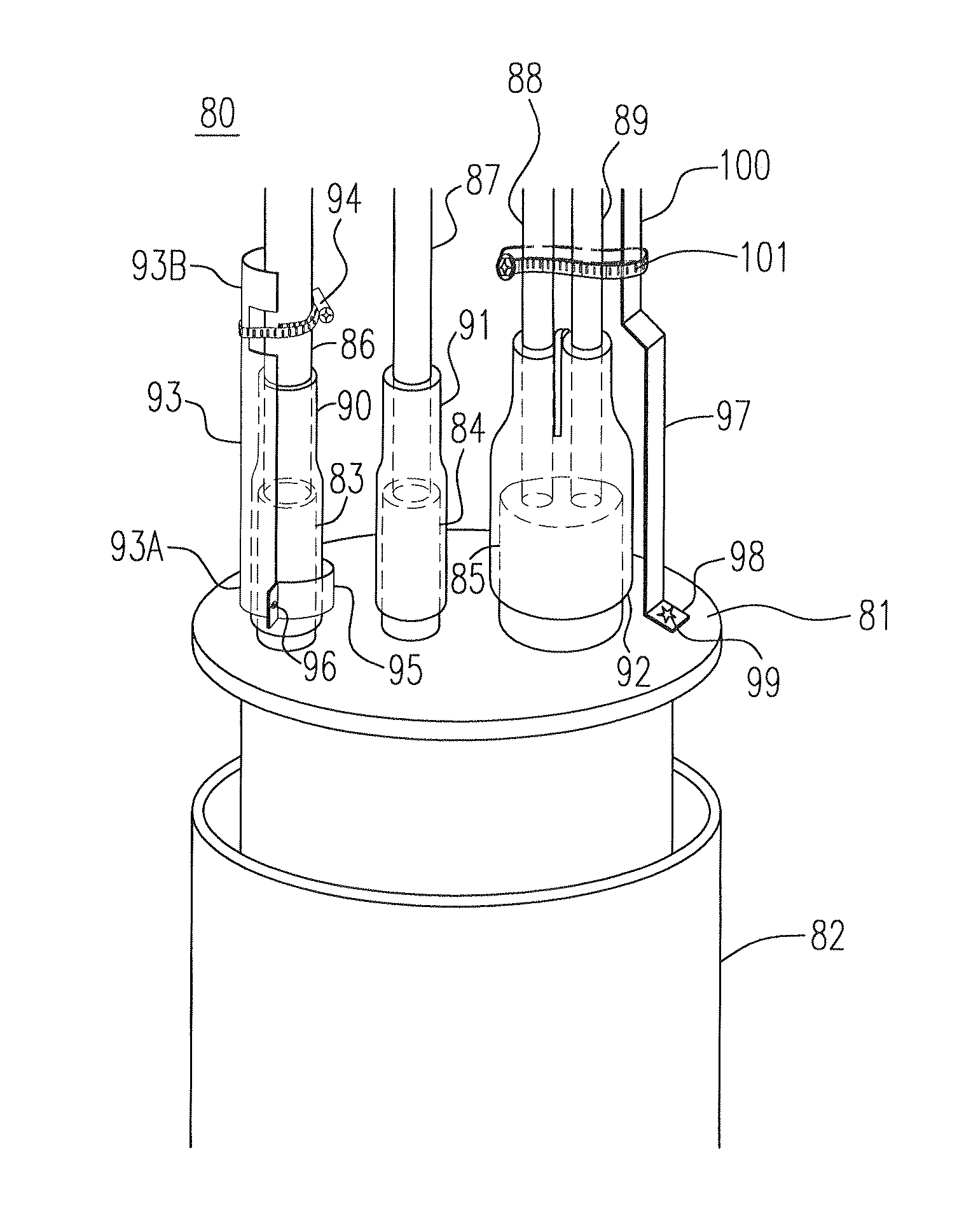
[0033]Please refer to FIG. 5, which is a diagram showing the cable fixture device of the communication cable splice box, shown in Embodiment 3 of the present invention. In FIG. 5, communication cable splice box 80 (abbreviated as “splice box” thereafter) at least is constructed of cable entry board 81, protective cover 82 (partially), hollow cylindrical tubes 83, 84, 85, flexible rubber shrinkable tube 90, 91, and cable fixture device. Similar to the illustrations in Embodiment 1 and 2, hollow cylindrical t...


PUM


Abstract

A waterproof communication cable connection box includes a protective cover, a cable pass-through end surface, a hollow cylindrical pipe formed on the cable pass-through end surface, an elastic rubber shrinking pipe, and a flexible hard plastic strip provided on the inner wall of the elastic rubber shrinking pipe. The plastic strip will be removed after a cable passes through the cable connection box so that the elastic rubber shrinking pipe closely covers the hollow cylindrical pipe and the cable part exposing outside of the hollow cylindrical pipe.

Description

CROSS-REFERENCE TO RELATED APPLICATION AND CLAIM OF PRIORITY[0001]The application claims the benefit of the International Patent Application No. PCT / CN2009 / 000257, filed on Mar. 10, 2009, in the World Intellectual Property Office, the disclosures of which are incorporated herein in their entirety by reference.FIELD OF THE INVENTION[0002]The present invention relates to a communication cable splice box having a shrinkable rubber tube waterproof device, especially one that ensures simple and safe construction, without the need of tools or a fire source, and the external diameter of the applicable cable extensively varies. The present invention is able to overcome the water leakage problems on the cable splice box in the current technology of the heat-shrink cable splice box, where the torched heat-shrink tube softens and loosens result from heating once more after a heat-shrink tube for cable entrance and seal was heated with torch and then the other heat-shrink tubes for cable entran...

Claims


Application Information

Patent Timeline
Patent Type & Authority Patents(United States)
IPC IPC(8): G02B6/44G02B6/00
CPCH02G15/1833H02G9/10H02G15/18G02B6/46
Inventor HSING, CHIHKUANG
Owner KOREA AEROSPACE INDUSTRIES
Why Eureka
Try Eureka