
Agent delivery catheter having an inflation bridge between two axially spaced balloons

a balloon and balloon catheter technology, applied in the field of catheters, can solve problems such as difficulty in providing the necessary operative distal end

Active Publication Date: 2009-08-13
ABBOTT CARDIOVASCULAR
View PDF7 Cites 24 Cited by
  • Summary
  • Abstract
  • Description
  • Claims
  • Application Information

AI Technical Summary

Benefits of technology

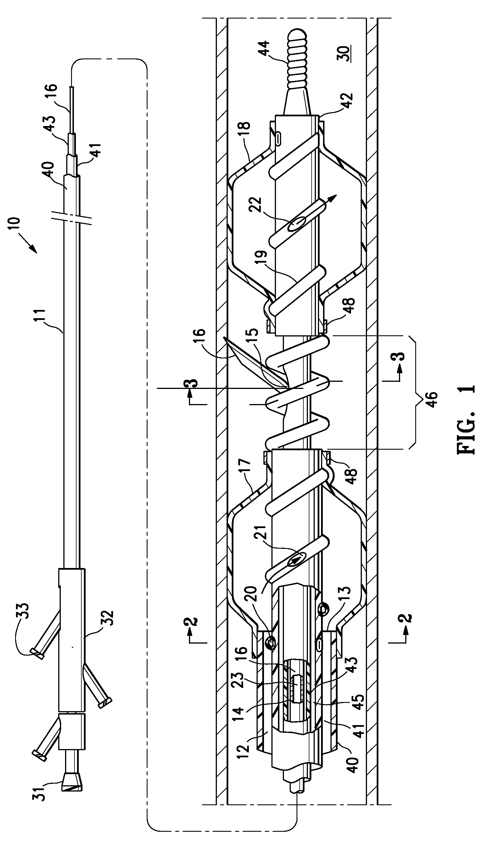
[0005]The invention is directed to an agent delivery catheter having two or more axially spaced balloons and an inflation bridge providing fluid communication between the two balloons. A catheter of the invention generally has a proximal balloon, a distal balloon, and a tube defining an inflation bridge lumen which is located in part within the inflatable interiors of the proximal and distal balloons, and which extends therebetween, and which has a proximal port within the proximal balloon interior and a distal port within the distal balloon interior to thereby provide for inflation of the distal balloon by placing the distal balloon interior in fluid communication with the proximal balloon interior of the shaft.
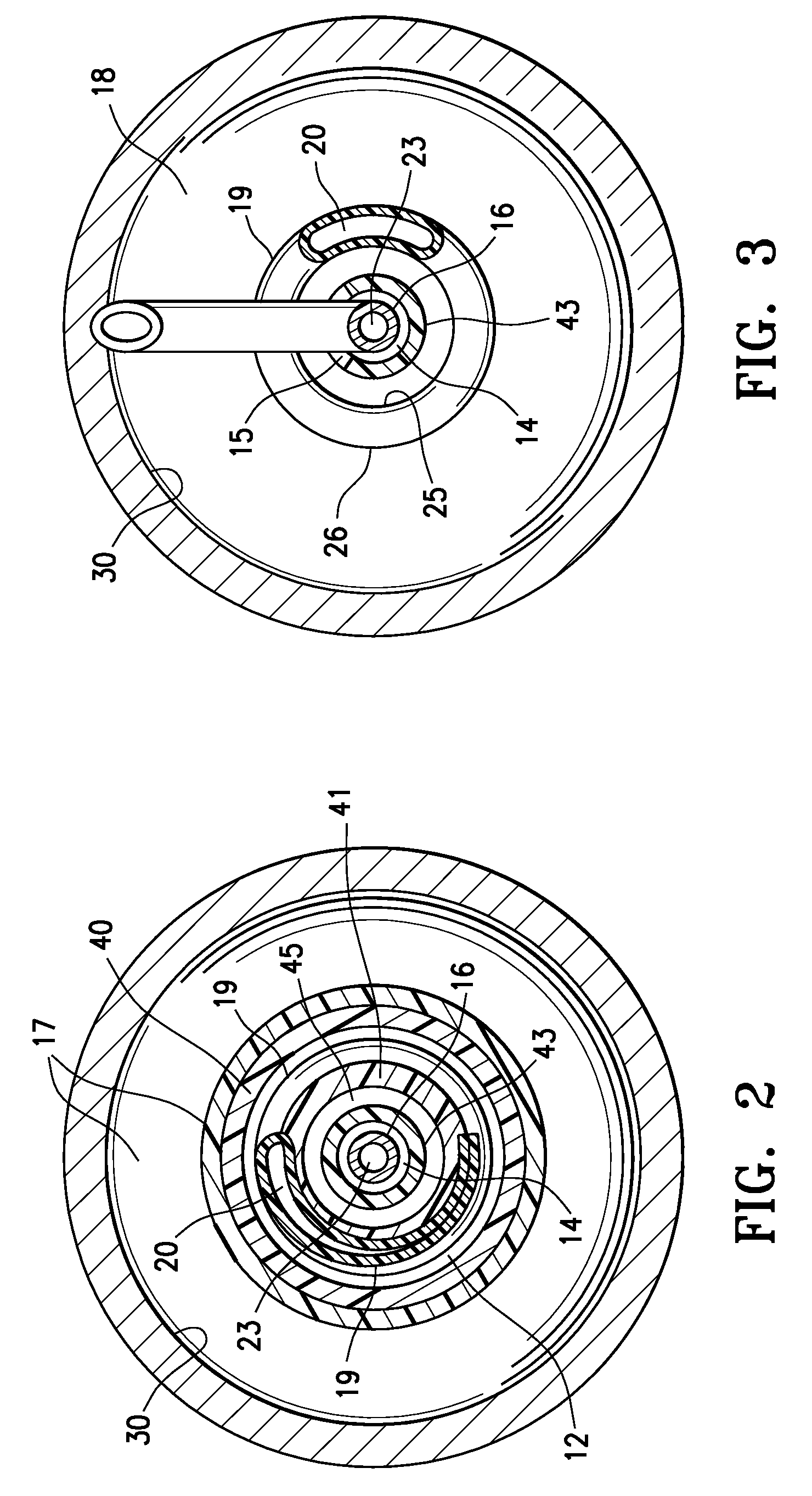
[0007]At least part of the length of the inflation bridge tube is on an outer surface of the shaft, optionally at least partially embedded in the shaft. The inflation bridge tube extends within at least a portion of the inflatable interior of each balloon, and in a presently preferred embodiment it extends helically through substantially the entire length (i.e., all or at least a majority of the length) of the inflatable interior of each balloon. Ports in the ends of the tube and / or through a sidewall of the tube allow inflation fluid from the inflation lumen of the shaft to flow into the inflation bridge tube lumen and then out of the inflation bridge tube lumen into the distal balloon interior. However, in a presently preferred embodiment, the inflation bridge tube is configured to prevent or minimize the risk of the tube causing some form of damage to (e.g., perforating) the balloon or the patient's anatomy. Additionally, the inflation bridge tube is preferably configured to provide for relatively fast transfer of inflation fluid to the distal balloon, while nonetheless providing ease of manufacture of a highly flexible, deliverable catheter. These and other advantages of the invention will become more apparent from the following detailed description of the invention and accompanying exemplary drawings.

Problems solved by technology

However, these are often competing considerations, making it difficult to provide the necessary operative distal end while still having good deliverability (i.e., ability to track within the patient's often tortuous vasculature to a desired location therein).

Method used


Image

  • Agent delivery catheter having an inflation bridge between two axially spaced balloons
  • Agent delivery catheter having an inflation bridge between two axially spaced balloons
  • Agent delivery catheter having an inflation bridge between two axially spaced balloons

Examples


Embodiment Construction

[0015]FIG. 1 illustrates an elevational, partially in section, view of an agent delivery catheter 10 embodying features of the invention, generally comprising an elongated catheter shaft 11 having a proximal end, a distal end, a distal shaft section, an inflation lumen 12 extending distally from the proximal end of the shaft to a distal end 13 located proximal to a distal end of the catheter, a needle-through lumen 14 slidably containing a hollow needle 16 therein, and at least one needle-through port 15, and a proximal balloon 17 on the distal shaft section with an inflatable interior located proximal to the needle-through port 15, and a distal balloon 18 which is on the shaft distal to the proximal balloon and which has an inflatable interior located distal to the needle-through port 15, and a tube 19 defining an inflation bridge lumen 20, extending between the inflatable interiors of the balloons 17, 18 from a location proximal to a location distal of the needle-through port 15. ...


PUM


Abstract

An agent delivery catheter having two or more axially spaced balloons and an inflation bridge providing fluid communication between the two balloons. The catheter generally has a proximal balloon, a distal balloon, and a tube defining an inflation bridge lumen which is located in part within the inflatable interiors of the balloons, and which extends therebetween, and which has a proximal port within the proximal balloon interior and a distal port within the distal balloon interior to thereby provide for inflation of the distal balloon by placing the distal balloon interior in fluid communication with the proximal balloon interior of the shaft.

Description

CROSS-REFERENCES TO RELATED APPLICATIONS[0001]NoneBACKGROUND OF THE INVENTION[0002]The invention relates to the field of medical devices, and more particularly to catheters, such as needle catheters or other elongated devices configured for inserting into a patient's body lumen to perform a diagnostic or therapeutic procedure, such as delivery of an agent to the coronary or peripheral vasculature.[0003]The delivery of therapeutic agents into various parts of the vascular system has been shown to be an effective method of treating vascular disease. A variety of agents can be delivered including anti-proliferative, anti-inflammatory, anti-neoplastic, anti-platelet, anti-coagulant, anti-fibrin, anti-thrombotic, anti-mitotic, antibiotic, anti-allergic, and antioxidant compounds. To treat a diseased section of the vessel, these agents could be delivered directly into the vessel wall adjacent to the diseased section, and / or into the perivascular space. Vascular regenerative therapies, suc...

Claims


Application Information

Patent Timeline
Patent Type & Authority Applications(United States)
IPC IPC(8): A61M25/10A61F2/958
CPCA61M25/0084A61M2025/0096A61M2025/0092A61M25/1011A61M25/0068A61M25/008A61M25/0082A61M25/04A61M25/1002A61M2025/0081A61M2025/0681A61M2025/1047A61M25/0013A61M25/0155A61M25/0606
Inventor NGUYEN, BINH T.VON OEPEN, RANDOLFEHRENREICH, KEVIN J.WEBLER, JR., WILLIAM E.MIN, SUNG WOOLUMAUIG, ROMMELYRIBARREN, TRAVIS R.
Owner ABBOTT CARDIOVASCULAR
Learn More