Control method and system of engine

a control method and engine technology, applied in the direction of electric control, braking system, instruments, etc., can solve the problems of nox emission, excessive temperature and pressure in the combustion chamber, and inability to effectively prevent any improper detonation or deterioration of nox emission

Inactive Publication Date: 2013-04-09
MAZDA MOTOR CORP
View PDF7 Cites 7 Cited by
  • Summary
  • Abstract
  • Description
  • Claims
  • Application Information

AI Technical Summary

Benefits of technology

[0005]The present invention has been devised in view of the above-described matters, and an object of the present invention is to provide a control method or a control device of an engine which can effectively prevent any improper detonation or deterioration of the NOx emission which may be caused by the compression self-ignition combustion in the range where the engine load is relatively high.
[0007]According to the present invention, since the first fuel injection is executed when the internal pressure of the combustion chamber drops to a certain degree after the exhaust top dead center, the injected fuel evaporates without combusting, so that the inside of the combustion chamber is cooled down properly by its evaporation heat. Then, the second fuel injection is executed subsequently under this state of the cooled combustion chamber. Thereby, any improper detonation, such as pre-ignition, can be effectively prevented in the high-engine load range in the homogeneous-charge-compression-ignition (HCCI) combustion mode by restraining the ignitability of the air-fuel mixture properly. Further, since the above-described cooling down of the inside of the combustion chamber by the first fuel injection promotes the reduction of the internal pressure, thereby the induction of the intake air, the induction volumetric efficiency can improve, and the combustion temperature decreases so properly that the NOx emission can improve.
[0008]According to an embodiment of the present invention, the amount of fuel injected through the first fuel injection is set to increase as the engine load becomes higher. Thereby, the cooling function by the first fuel injection can be improved in the high-engine load range where the temperature and internal pressure of the combustion chamber may increase, so that the detonation or the increase of NOx emission in the high-engine load range can be effectively prevented.
[0009]According to another embodiment of the present invention, the above-described specified load of the engine load and the specified pressure of the internal pressure of the combustion chamber are set to be lower values respectively as the temperature of cooling water of the engine becomes higher. Thereby, the execution timing of the first fuel injection can be adjusted properly according to the temperature condition of the engine, so that the detonation can be effectively prevented by performing the proper cooling function by the first fuel injection.
[0010]According to another embodiment of the present invention, the control method of an engine further comprises determining a low-engine load range where the engine load is lower than the specified load in the homogeneous-charge-compression-ignition combustion mode, executing a first fuel injection from the fuel injector in the low-engine load range at a point before the top dead center of the exhaust stroke during the minus valve overlap period, and executing a second fuel injection from the fuel injector in the low-engine load range at a point after an execution timing of the first fuel injection. Thereby, even in a situation in which the engine load is relatively low so that the self ignition tends not to occur easily, an auxiliary combustion caused by the first fuel injection can increase the temperature inside the combustion chamber. Accordingly, the compression self-ignition combustion caused by the second fuel injection can be effectively promoted, so that the combustion stability can be further improved.
[0011]According to another embodiment of the present invention, the amount of fuel injected through the first fuel injection in the low-engine load range is set to decrease as the engine load becomes higher. Thereby, since the combustion energy produced by the first fuel injection decreases according to the engine load, the promotion of combustion with the high temperature inside the combustion chamber can be achieved at an appropriate level according to the engine load, so that the combustion stability in the low-engine load range can be ensured properly.

Problems solved by technology

However, if the first fuel injection is executed at the above-described timing (after the closure timing of the exhaust valve and before the top dead center of the exhaust stoke of the engine) disclosed in the above-described publication in a range where the engine load is relatively high, there is a concern that the injected fuel may combust near at the timing of the top dead center of the exhaust stoke, thereby the combustion chamber may have a too-high temperature and a too-high pressure.
This state would possibly cause a detonation (abnormal combustion), such as pre-ignition, which may be initiated by the above-described second fuel injection.
This state would also prevent the induction of the sufficient amount of air into the combustion chamber during the intake stroke, so that there is a concern that the combustion temperature may increase so much that the NOx emission would deteriorate.

Method used


Image

  • Control method and system of engine
  • Control method and system of engine
  • Control method and system of engine

Examples


Embodiment Construction

[0023]Hereinafter, a preferred embodiment of the present invention will be described referring to the accompanying drawings.

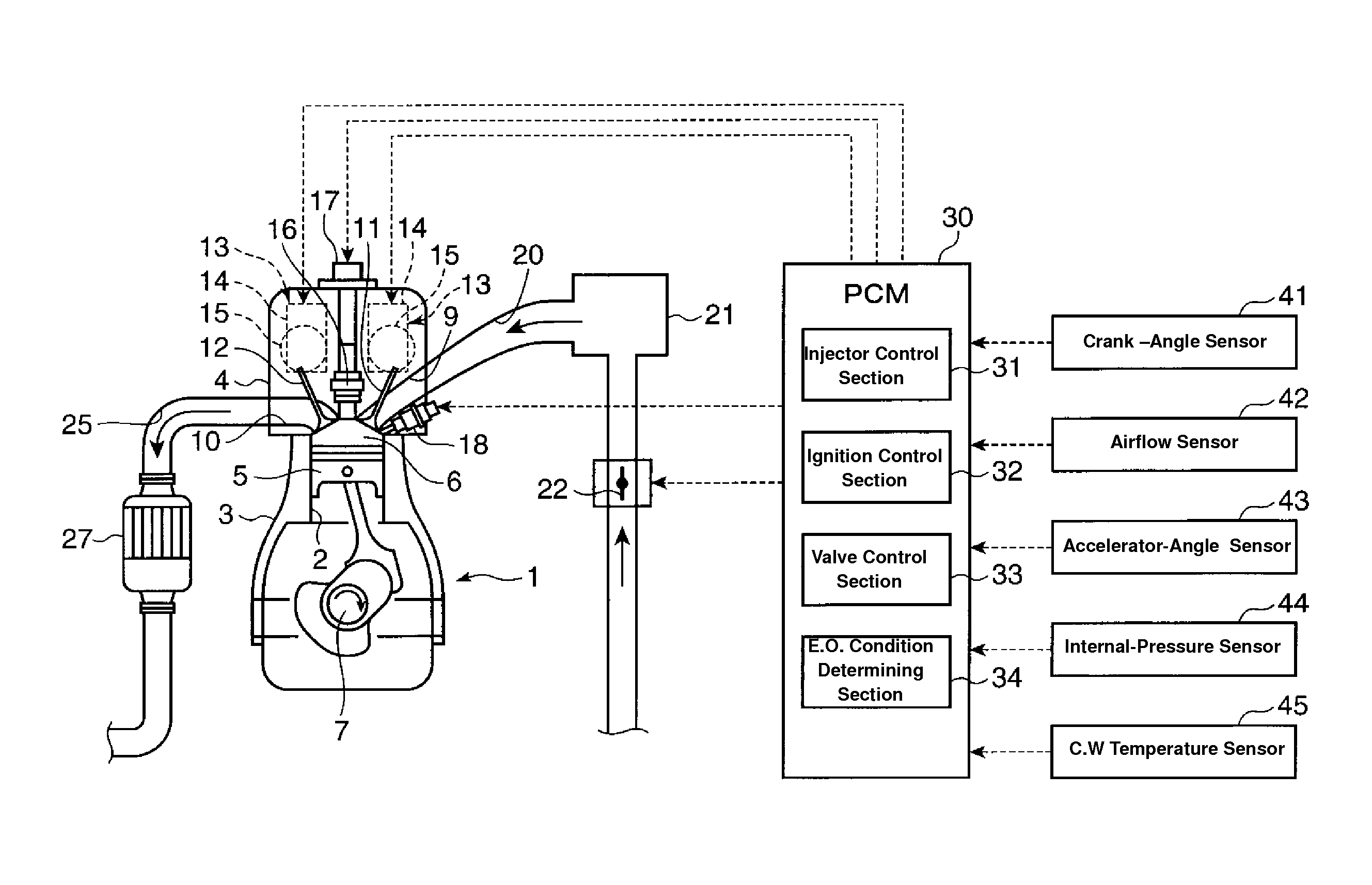
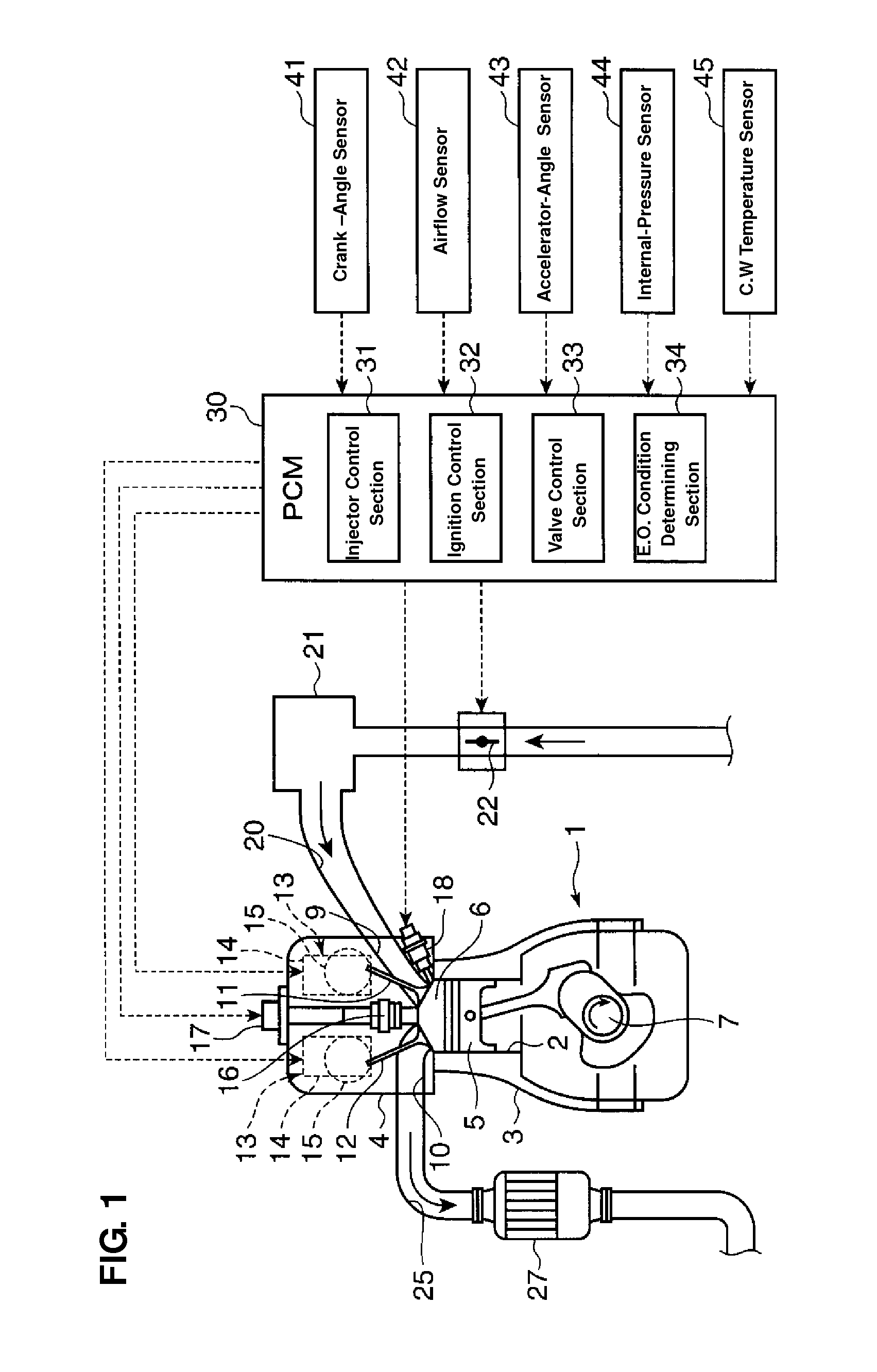
[0024]FIG. 1 is a schematic diagram showing a whole constitution of an engine to which a control method of the present invention is applied. The engine shown in this figure, which is a multi-cylinder gasoline engine, comprises an engine body 1 which includes a cylinder block 3 having plural cylinders 2 (only one of them illustrated in FIG. 1) which are arranged in a direction perpendicular to a paper surface, and a cylinder head 4 which is arranged on the cylinder block 3. A piston 5 is inserted into each of the cylinders 2 of the engine body 1, and a combustion chamber 6 having a specified volume is formed between a top face of the piston 5 and a bottom face of the cylinder head 4. The piston 5 is connected to a crank shaft 7 via a connecting rod so that the crank shaft 7 rotates around its axis according to a reciprocating movement of the piston 5.

[0025]An in...


PUM


Abstract

When it is determined that an engine operating condition is in a high-engine load HCCI range (A2) where an engine load is higher than a specified load X1 within a HCCI range A where a compression self combustion is performed, an after-TDC injection F2s is executed at a point T1 when an internal pressure of a combustion chamber drops below a specified pressure Y after the top dead center of an exhaust stroke during a minus valve overlap period NVO during which intake and exhaust valves are both closed. Then, a main injection F2m as a main injection is executed. Accordingly, any improper detonation or deterioration of NOx emission which may be caused by the compression self-ignition combustion in the range where the engine load is relatively high can be prevented.

Description

BACKGROUND OF THE INVENTION[0001]The present invention relates to a control method and device of an engine which has a homogeneous-charge-compression-ignition (HCCI) combustion mode in which a premixed air-fuel mixture is compressed in a combustion chamber so that a self-ignition of the mixture is performed without requiring spark from a spark plug, and a minus valve overlap period during which an intake valve and an exhaust valve are both closed at a transitional time from an exhaust stroke to an intake stroke of the engine.[0002]Conventionally, as disclosed in U.S. Pat. No. 6,425,367, the compression self-ignition gasoline internal combustion engine, in which a fuel injector to inject fuel directly into a combustion chamber is provided and the air-fuel mixture is compressed by a piston so that a self-ignition of the mixture is performed, is known. Herein, the minus valve overlap period during which an intake valve and an exhaust valve are both closed at a transitional time from an...

Claims


Application Information

Patent Timeline
Patent Type & Authority Patents(United States)
IPC IPC(8): B60T7/12
CPCF02D13/0207F02D13/0265F02D41/3035F02D41/402Y02T10/128Y02T10/44Y02T10/18Y02T10/12Y02T10/40
Inventor YAMASHITA, HIROYUKISETO, MASATOSHIKAWAI, YUSUKE
Owner MAZDA MOTOR CORP
Why Eureka
Try Eureka