Air-intake structure of an engine

a technology of air intake and engine, which is applied in the direction of propulsion parts, vehicle components, propulsion unit gas exhaust, etc., can solve the problems of difficult to obtain a sufficient air intake amount for the engine quickly, and difficulty in so as to achieve the effect of ensuring a sufficient amount of air intake for the engin

Active Publication Date: 2013-04-16
KAWASAKI MOTORS LTD
View PDF2 Cites 9 Cited by
  • Summary
  • Abstract
  • Description
  • Claims
  • Application Information

AI Technical Summary

Benefits of technology

[0008]The present invention addresses the above described conditions, and an object of the present invention is to provide a vehicle which is capable of obtaining a sufficient air-intake amount required for an engine quickly during low-speed driving when a ram pressure is low.

Problems solved by technology

However, since a portion of the duct which is located upstream of the air cleaner box in an air flow direction is long and a passage resistance of the air-intake passage is high, it is sometimes difficult to ensure a sufficient air-intake amount required for the engine during low-speed driving when the ram pressure is low.
However, since the vehicle is exiting a corner at a low speed, the ram pressure is low and the passage resistance is significantly high, it is difficult to obtain a sufficient air-intake amount required for the engine quickly, even when the throttle valve is opened.

Method used


Image

  • Air-intake structure of an engine
  • Air-intake structure of an engine
  • Air-intake structure of an engine

Examples


embodiment 1

[Construction of Motorcycle]

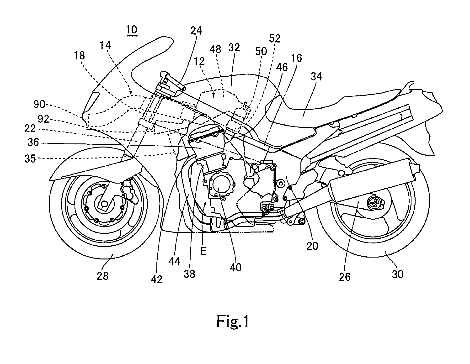
[0042]FIG. 1 is a left side view of a construction of an entire motorcycle 10 which is a vehicle according to Embodiment 1

[0043]Referring now to FIG. 1, the motorcycle 10 includes a main frame member 16, a head pipe 18 provided at the front portion of the main frame member 16 and a pair of right and left pivot frame members 20 provided at the rear portion of the main frame member 16. A steering shaft (not shown) is rotatably inserted into the head pipe 18. A front fork 22 and a steering handle 24 are attached to the steering shaft. A pair of right and left swing arms 26 are attached to the pivot frame members 20, respectively. A front wheel 28 is mounted to the lower end portion of the front fork 22. A rear wheel 30 is mounted to the rear end portions of the swing arms 26. A fuel tank 32 and a seat 34 are arranged at the upper portion of the main frame member 16 such that the fuel tank 32 is disposed forward relative to the seat 34. An engine E is mounted...

embodiment 2 , 3

Embodiment 2, 3

[0077]FIG. 7A is a cross-sectional view showing a configuration of an on-off valve 140 of the motorcycle according to Embodiment 2. FIG. 7B is a perspective view showing a configuration of the on-off valve 140 of the motorcycle according to Embodiment 2. Although the on-off valve 100 configured to permit and inhibit the air flow through the sub-passage R2 is a one-way valve for permitting only the air flow from the sub-inlet 92 toward the joint section 94, in Embodiment 1, the on-off valve 140 in Embodiment 2 is a two-way valve for permitting air flow from the joint section 94 toward the sub-inlet 92 as well as the air flow from the sub-inlet 92 toward the joint section 94.

[0078]Referring to FIG. 7, the on-off valve 140 includes a plate-like valve body 142 having substantially the same shape as that of a passage cross-section of the sub-passage R2 in a closed position P0 in which the valve body 142 closes the sub-passage R2, a support portion 144 provided at the sub-d...

embodiment 4 , 5

Embodiment 4, 5

[0084]FIG. 9 is a cross-sectional view showing a configuration of an on-off valve 160 in a motorcycle according to Embodiment 4. FIG. 10 is a cross-sectional view showing a configuration of an on-off valve 170 in a motorcycle according to Embodiment 5.

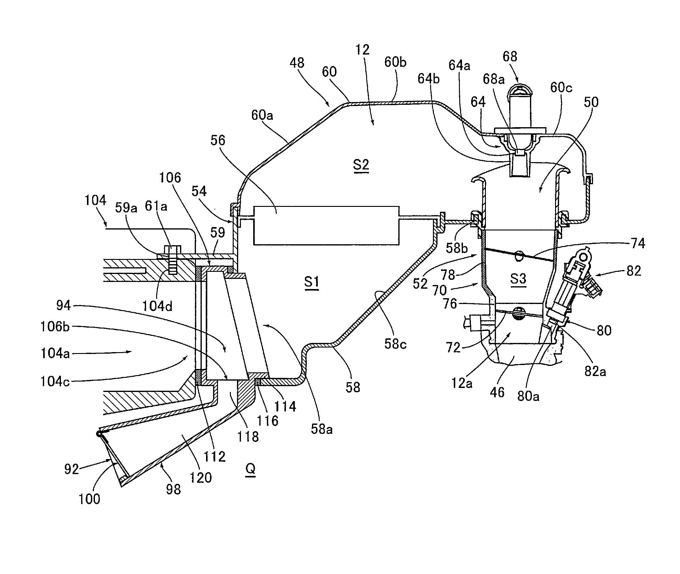
[0085]Although the on-off valves 100, 140 and 150 are provided at the front end portion of the second portion 120 in the vicinity of the sub-inlet 92 as shown in FIGS. 6, 7, and 8, an on-off valve may be positioned to permit and inhibit the air flow through the sub-duct component 98, regardless of whether the on-off valve is a one-way valve or a two-way valve. For example, as shown in FIG. 9, in Embodiment 4, the on-off valve 160 may be provided to open and close an opening 106b formed on the inner surface of the bottom portion of the downstream duct member 106. Or, as shown in FIG. 10, in Embodiment 5, a hole-shaped sub-duct portion 172 may be formed in the lower case 58 (guide surface 58c in Embodiment 5) of the air cl...


PUM


Abstract

A vehicle includes a duct structure configured to take in air from outside; an air cleaner including an air filter configured to clean the air guided to the air cleaner through the duct structure; a throttle device including a throttle valve for controlling a flow rate of the air guided to the throttle device through the air cleaner; and an engine including an intake port configured to suction the air guided to the engine through the throttle device; the duct structure including: a main inlet configured to take in air therethrough from outside by utilizing a ram pressure; a main passage extending from the main inlet to the air filter; a sub-inlet configured to take in air therethrough from outside; and a joint section located upstream of the air filter, the air flowing from the sub-inlet being joined to the air in the main passage, at the joint section.

Description

CROSS-REFERENCE TO RELATED APPLICATION[0001]The present application claims priority to Japanese Patent Application No. 2009-299245 filed on Dec. 29, 2009 which is hereby incorporated by reference in its entirety for all purposes.BACKGROUND ART[0002]1. Field of the Invention[0003]The present invention relates to a vehicle including a duct configured to take in air from outside by utilizing a ram pressure.[0004]2. Description of the Related Art[0005]An engine mounted in a vehicle such as a motorcycle includes a cylinder head having a combustion chamber. An air-intake passage is coupled to an intake port of the combustion chamber to guide air and fuel to the combustion chamber. Typically, the air-intake passage includes an air cleaner box of an air cleaner, an air-intake duct, and a throttle body of a throttle device which are coupled to each other in this order from upstream side in an air flow direction. Inside the throttle body, a throttle valve for controlling an air-intake amount ...

Claims


Application Information

Patent Timeline
Patent Type & Authority Patents(United States)
IPC IPC(8): B60K13/02
CPCB60K13/02B60Y2200/12
Inventor MATSUDA, YOSHIHARUOGAWA, YUTO
Owner KAWASAKI MOTORS LTD
Why Eureka
Try Eureka