
Method for riveting two cover plate elements of a torsional vibration damper arrangement

a technology of torsional vibration damper and cover plate, which is applied in the direction of mechanical equipment, manufacturing tools, couplings, etc., to achieve the effect of stable holding of the spacer rivet elemen

Active Publication Date: 2013-04-23
ZF FRIEDRICHSHAFEN AG
View PDF1 Cites 0 Cited by
  • Summary
  • Abstract
  • Description
  • Claims
  • Application Information

AI Technical Summary

Benefits of technology

The patent text describes a technique for riveting two structural components parts together. The technique involves using a spacer rivet element that is designed to form a rivet head when acted upon by a riveting force. The two structural component parts are held in a desired distance from each other during the riveting process, ensuring that they are not moved relative to each other. This is achieved by supporting one of the structural component parts from its inner side using a second supporting arrangement that extends through the other structural component part. The technique also involves using rivet openings that are overdesigned, so that the rivet element cannot tilt or shift axially during the process. This ensures a uniform and reliable riveting process.

Problems solved by technology

Since this is not the function of these spacer rivet elements 46′, this would only run the unnecessary risk that stresses occur in the area of step-like transitions when the spacer rivet elements are loaded which could result in breakage.

Method used


Image

  • Method for riveting two cover plate elements of a torsional vibration damper arrangement
  • Method for riveting two cover plate elements of a torsional vibration damper arrangement
  • Method for riveting two cover plate elements of a torsional vibration damper arrangement

Examples


Embodiment Construction

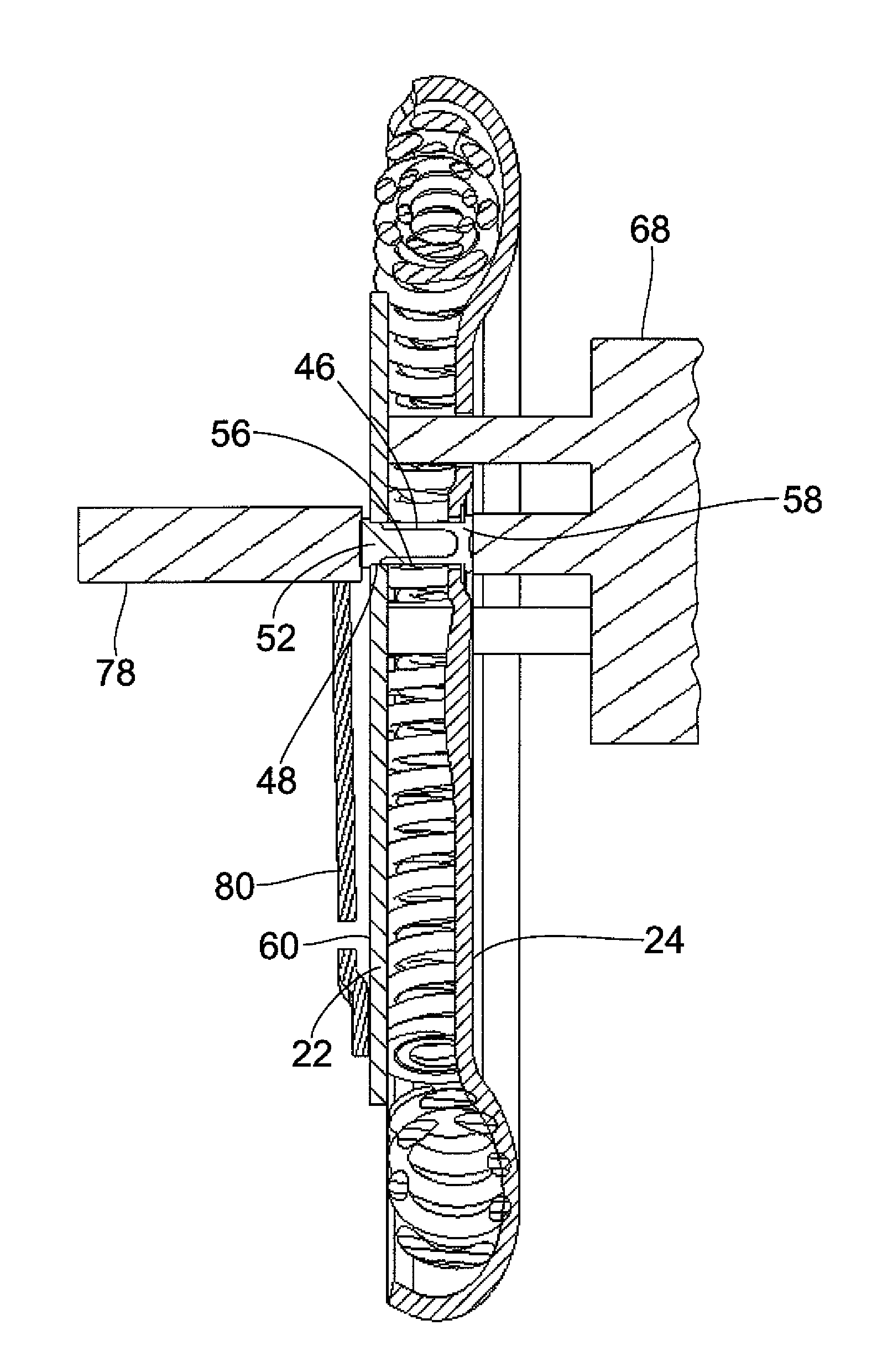
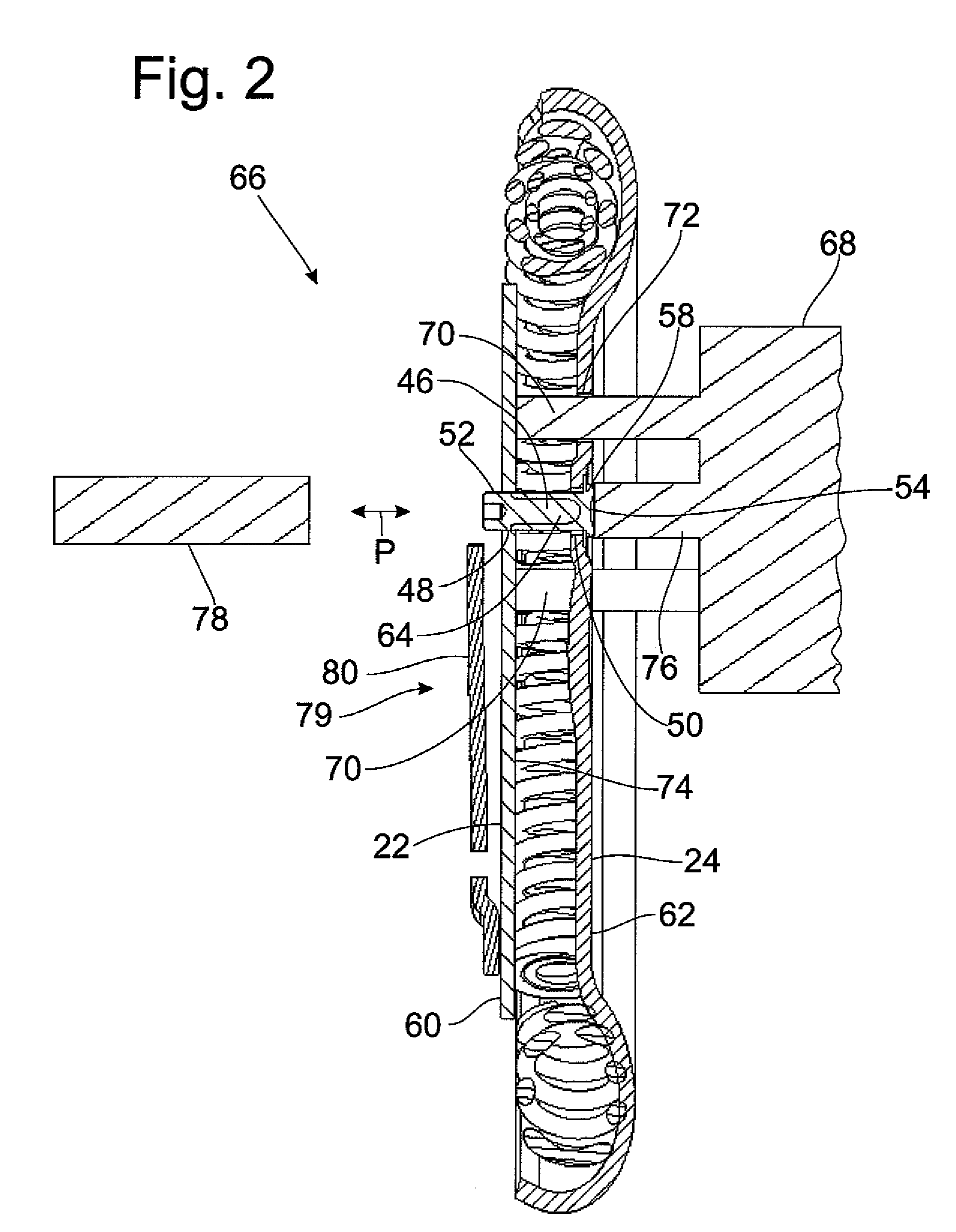
[0050]With reference to different examples, the following description will illustrate how two structural component parts which are made of sheet metal material can be connected to one another by one spacer rivet element, but generally by a plurality of spacer rivet elements, in such a way that a specified maximum distance between the two structural component parts to be connected to one another is ensured by rivet elements of this kind. The two structural component parts to be connected to one another in the example are the cover plate elements, or cover plates, of a torsional vibration damper arrangement such as that which was described by way of example with reference to FIG. 1. Of course, other structural component parts in other fields of application can also be connected to one another in the manner described in the following.

[0051]FIG. 2 shows the two cover plate elements 22, 24 which are arranged opposite one another and which also are, or can be, fixedly connected to one ano...


PUM

PropertyMeasurementUnit
distanceaaaaaaaaaa
areaaaaaaaaaaa
forceaaaaaaaaaa

Abstract

A method for riveting two structural component parts arranged with their inner sides facing one another and with their outer sides facing away from one another at a distance from one another by at least one spacer rivet element. Positioning the at least one spacer rivet element at the two structural component parts such that rivet element end areas extend through rivet openings provided in the structural component parts to be associated with the rivet element end areas. Supporting a rivet element end area at the outer side of one of the structural component parts. Supporting the other of the structural component parts at its inner side. Applying a riveting force to the other rivet element end area to deform at least one rivet element end area and to form a rivet head.

Description

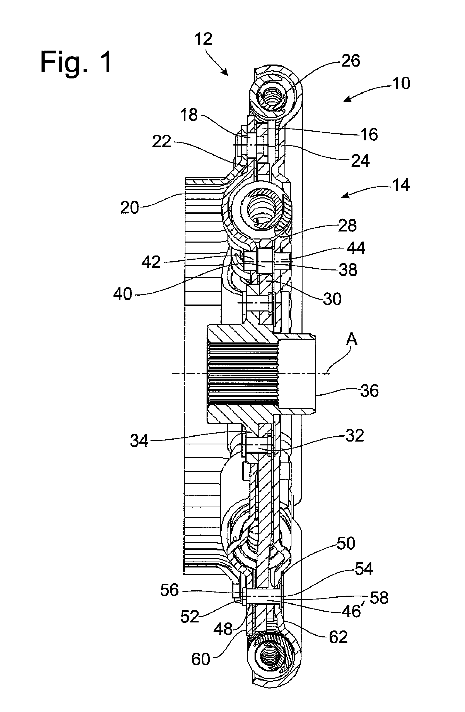
BACKGROUND OF THE INVENTION[0001]1. Field of the Invention[0002]The present invention is directed to a method for riveting two structural component parts, which are arranged so that their inner sides face one another and their outer sides face away from one another, in particular cover plate elements of a torsional vibration damper arrangement, at a distance from one another by at least one spacer rivet element.[0003]2. Description of the Related Art[0004]FIG. 1 is a longitudinal sectional view of a torsional vibration damper arrangement, designated in its entirety by 10, such as is used in the torque transmission path between a lockup clutch in a hydrodynamic torque converter and a driven shaft such as, e.g., the transmission input shaft, or generally in a wet multiple-disk clutch or the like. The torsional vibration damper arrangement 10 is constructed in two-tiered manner with two torsional vibration damper areas 12, 14 acting in series. An input area of the radially outer first ...

Claims


Application Information

Patent Timeline
Patent Type & Authority Patents(United States)
IPC IPC(8): B21J15/02B21D39/00
CPCB21J15/02B21J15/14F16F15/1203F16F2226/04Y10T29/49943Y10T29/49956Y10T29/5118Y10T403/4966Y10T403/4933
Inventor WICKEL, CHRISTIAN
Owner ZF FRIEDRICHSHAFEN AG
Learn More