AI technical title is built by Patsnap AI team. It summarizes the technical point description of the patent document.
a technology of induction drive and ignition system, which is applied in the direction of mechanical equipment, machines/engines, lighting and heating apparatus, etc., can solve the problems of slow propagation of the flame front, reducing efficiency, and most of these approaches still suffer from limitations
Inactive Publication Date: 2013-04-23
CONTOUR HARDENING
View PDF43 Cites 9 Cited by
Summary
Abstract
Description
Claims
Application Information
AI Technical Summary
This helps you quickly interpret patents by identifying the three key elements:
Problems solved by technology
Method used
Benefits of technology
Benefits of technology
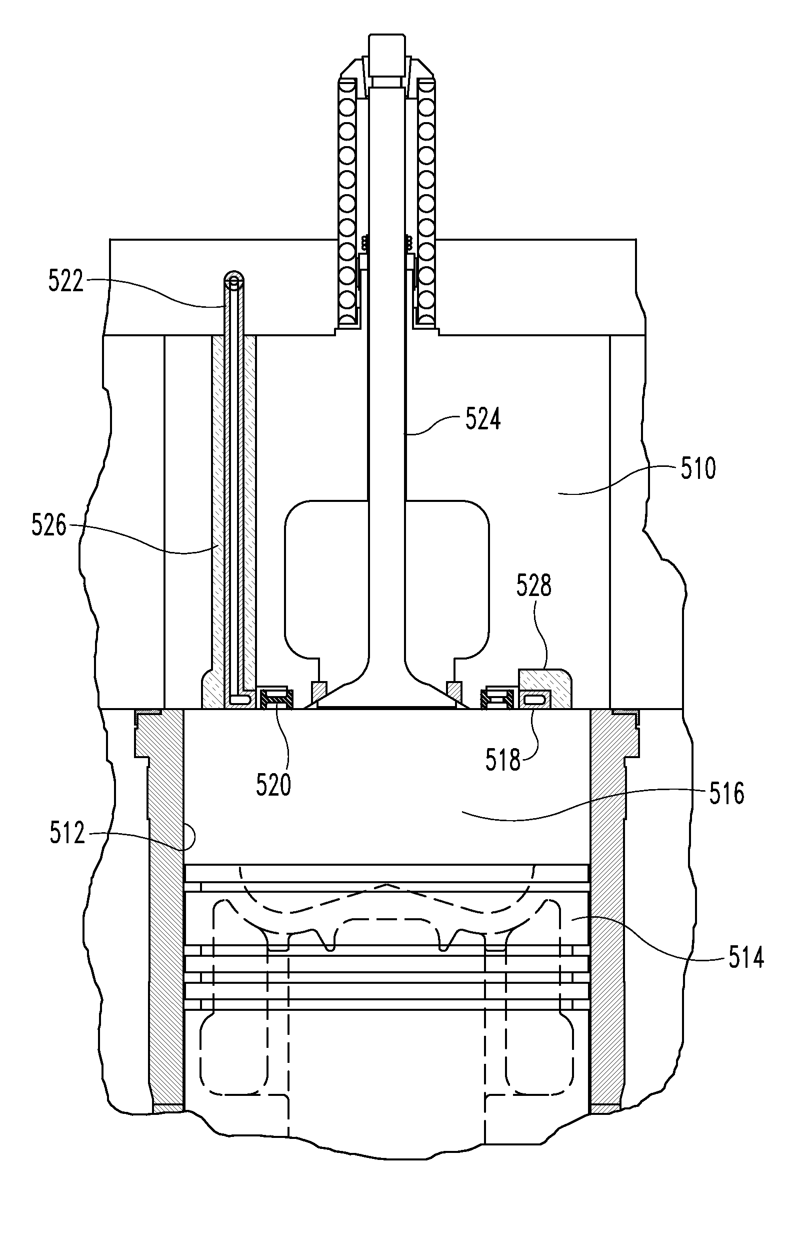
[0012]The present invention utilizes the rapid heat rise associated with metals affected by a electromagnetic field. One embodiment of the present invention goes beyond a single source ignition device through the use of extremely rapid and accurately controlled induction heating for a heat source that is unrestrained by conventional point ignition principles. The induction driven heat source offers a wide selection of its geometry so that it can be deployed throughout the combustion chamber. This permits the flame front to be expanded because there are multiple ignition sources or locations.
Problems solved by technology
However, one drawback with fuels of this type is the slow propagation of the flame front making it necessary for ignition timing to be well in advance of top dead center (TDC) to be sure all of the mixture is combusted.
This in turn reduces efficiency as the combustion pushes in one direction against the piston that is moving in the opposite direction as it moves toward TDC.
However, most of these approaches still suffer from the limitation that they are in fact point, or near point, initiators of combustion.
Another problem exists related to diesel engines and their inability to start in cold weather.
However, when the cylinder head and cylinder block are cold, they serve as a heat sink, absorbing a portion of the heat generated by the compression.
Because glow plugs are essentially resistive loads that emit heat when a current is run through them, the pre-heating process can take some time: up to 20 seconds.
Method used
Image
Click on the blue label to locate the original text in one second.
Reading with bidirectional positioning of images and text.
Examples
Embodiment Construction
[0052]For the purposes of promoting an understanding of the disclosure, reference will now be made to the embodiments illustrated in the drawings and specific language will be used to describe the same. It will nevertheless be understood that no limitation of the scope of the disclosure is thereby intended, such alterations and further modifications in the illustrated device and its use, and such further applications of the principles of the disclosure as illustrated therein being contemplated as would normally occur to one skilled in the art to which the disclosure relates.
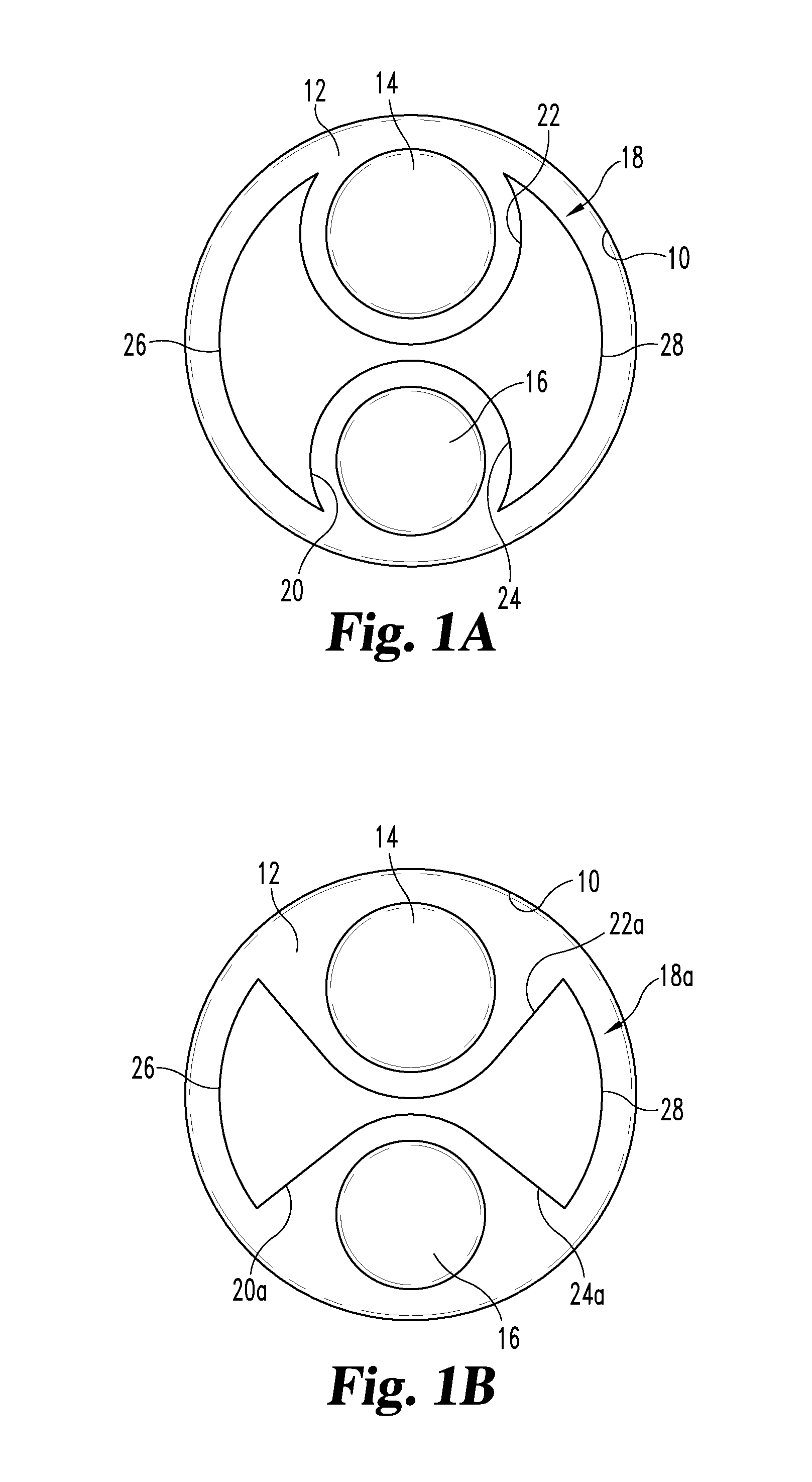
[0053]FIG. 1A shows an example of a typical combustion chamber configuration wherein the chamber 10 is defined by a cylinder head 12 having an intake valve 14 and an exhaust valve 16 to respectively admit a combustible mixture and to exhaust the motive fluid after the mixture has gone through combustion. The process of combustion transfers heat energy in the form of tangential force to a piston (not shown) connec...
PUM
Abstract
An induction driven ignition system with a heating element located near the combustion chamber of a reciprocating internal combustion engine. The heating element is adjacent an electrical conductor which receives current at frequencies between 100 kHz to 500 kHz. The induction driven ignition system causes the heating element to rapidly and accurately heat up to very high temperatures. The heating element may be positioned and arranged to provide combustion initiation over a wide area.
Description
CROSS-REFERENCE TO RELATED APPLICATIONS[0001]This application is a continuation-in-part of application Ser. No. 12 / 687,520, filed Jan. 14, 2010 now U.S. Pat. No. 8,181,618, which is a continuation of application Ser. No. 12 / 252,719, filed Oct. 16, 2008, now U.S. Pat. No. 7,647,907, which is a continuation-in-part of application Ser. No. 11 / 951,875, filed Dec. 6, 2007, now U.S. Pat. No. 7,533,643, which claims the benefit of U.S. Provisional Application No. 60 / 873,359, filed Dec. 7, 2006, all of which are hereby incorporated by reference in their entireties.BACKGROUND OF THE INVENTION[0002]The present invention relates to the field of ignition sources and more particularly to ignition sources used in internal combustion engines.[0003]In the field of internal combustion engines, especially the reciprocating type, a measured quantity of fuel and air is compressed and ignited either by an external ignition source or by the heat of compression. The engine in which the air / fuel mixture is...
Claims
Application Information
Patent Timeline
Application Date:The date an application was filed.
Publication Date:The date a patent or application was officially published.
First Publication Date:The earliest publication date of a patent with the same application number.
Issue Date:Publication date of the patent grant document.
PCT Entry Date:The Entry date of PCT National Phase.
Estimated Expiry Date:The statutory expiry date of a patent right according to the Patent Law, and it is the longest term of protection that the patent right can achieve without the termination of the patent right due to other reasons(Term extension factor has been taken into account ).
Invalid Date:Actual expiry date is based on effective date or publication date of legal transaction data of invalid patent.

