
Multiple tension reducing sprockets in a chain and sprocket system

a technology of sprockets and sprockets, which is applied in the direction of valve drives, gearing, hoisting equipment, etc., can solve the problems of repeating tension changes, increasing chain tensions and tension changes, and often generated audible sound frequencies creating undesirable noise, so as to increase the effect of tension excitation, and reduce the maximum chain tension

Active Publication Date: 2013-04-30
BORGWARNER INC
View PDF114 Cites 5 Cited by
  • Summary
  • Abstract
  • Description
  • Claims
  • Application Information

AI Technical Summary

Benefits of technology

[0019]In the sprocket systems described herein, two or more tension reducing sprockets are oriented relative to each other and are provided with root or pitch radii patterns that cooperatively reduce, and in some instances cancel, maximum chain tensions in chain and sprocket systems having two or more resonance modes. In one aspect, the at least two tension reducing sprockets provide root or pitch sequences and are oriented to reduce maximum chain tensions in one resonance mode relative to the tensions at such mode using a straight sprocket in such system, without significantly increasing the effect of tension excitations from sources outside of the chain and sprocket system at other resonance modes. In another aspect, the tension reduction sprockets are oriented with each other so that tensions will be reduced at a second (or higher) resonance mode relative to the tensions at such mode using a straight sprocket(s), without significantly increasing the maximum chain tensions at a first resonance mode by more than 20%, preferably not more than 10% and most preferably not more than about 0%. Hence, two or more tension reducing sprockets may be used to reduce tensions at one resonance mode from sources outside the chain and sprocket system while minimizing tension increases at another (or multiple) resonance mode(s).

Problems solved by technology

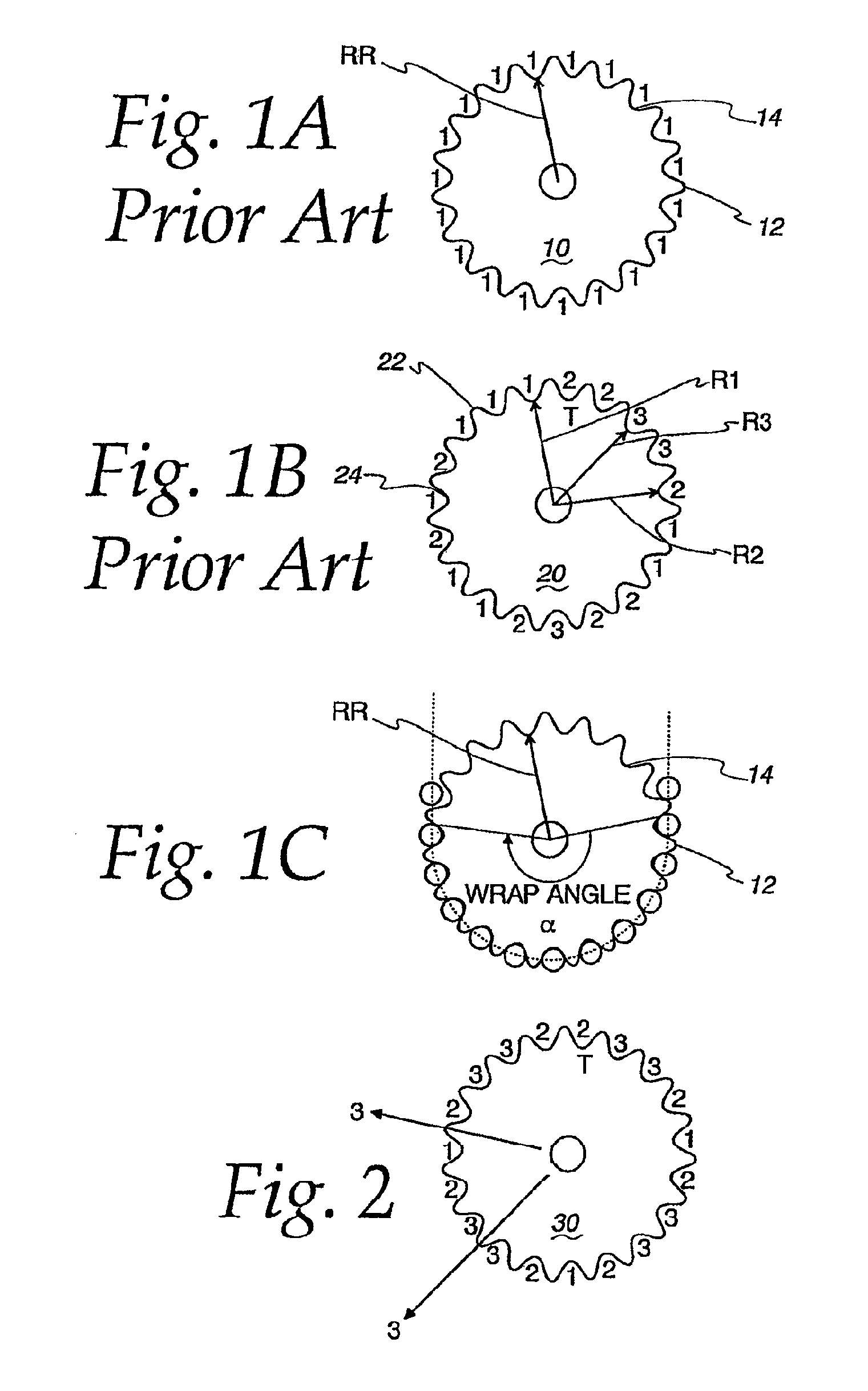
However, it has been found that as a chain rotates around a straight sprocket, audible sound frequencies creating undesirable noise are often generated as the chain teeth, pins or rollers connecting the links of the chain contact the sprocket teeth and impact sprocket engagement surfaces or the roots disposed between adjacent teeth of the sprockets.
For example, in automotive timing chain systems, it has been observed from chain tension measurements that the engagement and disengagement of each sprocket tooth or root with the chain often results in repeating tension changes.
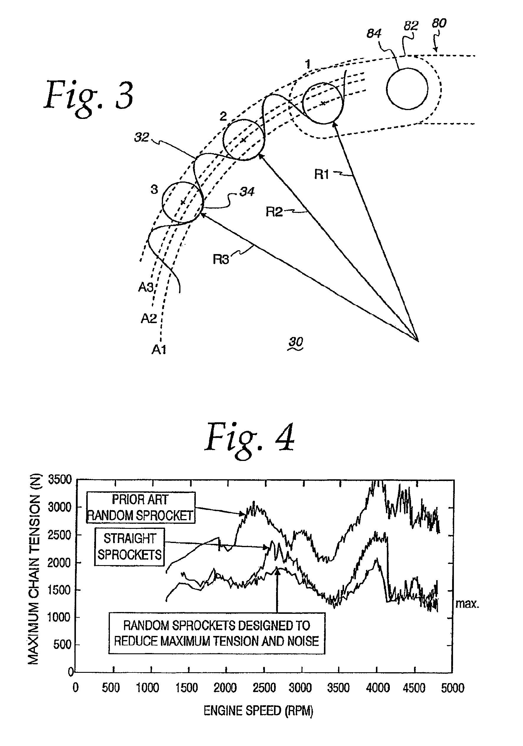
Random sprockets designed principally for noise reduction often cause increases in chain tensions and tension changes as compared to the maximum tensions imparted to the chain by straight sprockets.
However, reducing the pitch order of a sprocket may result in concentrating the tensional forces imparted to the chain by the sprocket over the lower orders of the sprocket.
This often results in increased chain tensions corresponding to the lower orders of the random sprocket.
Such increased chain tensions at the lower sprocket orders frequently cause the overall maximum chain tension force exerted on the chain and sprocket to increase.
As a consequence, a chain and sprocket system subjected to such tensions typically will experience greater wear and increased opportunities for failure, as well as other adverse effects, due to the concentration of the tensional forces in the lower orders.
The presence of multiple resonance modes may complicate efforts to reduce overall chain tensions.
In some drive systems, the resonance mode at relatively high system oscillation frequencies does not contribute enough tension to the overall maximum chain tension to make it a concern for chain durability.

Method used


Image

  • Multiple tension reducing sprockets in a chain and sprocket system
  • Multiple tension reducing sprockets in a chain and sprocket system
  • Multiple tension reducing sprockets in a chain and sprocket system

Examples


example 1

How Sprocket Orientation Affects the Performance of Two Tension Reducing Sprockets on First Mode

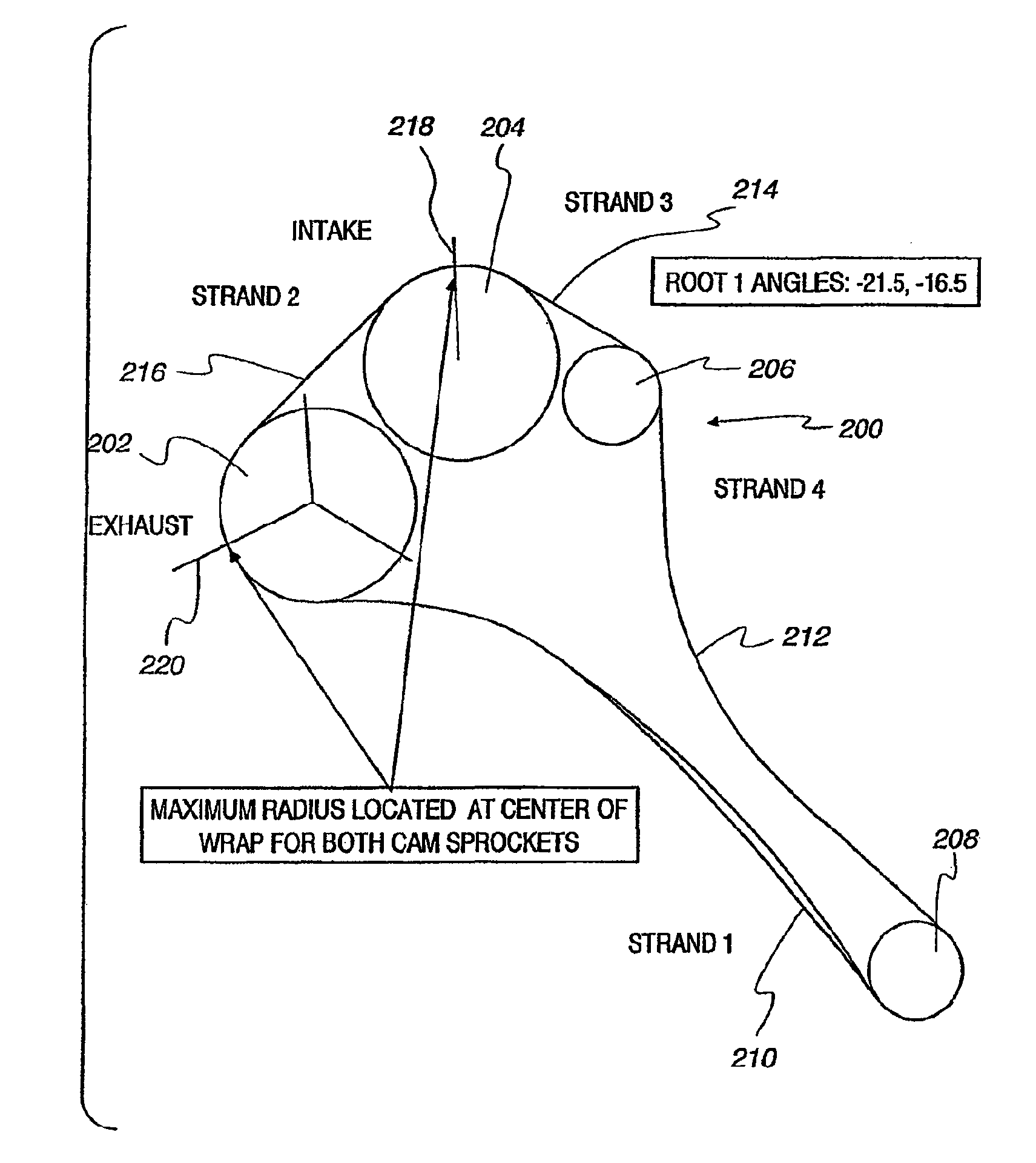
[0110]FIG. 7 shows a system 200 with two third order tension reducing sprockets 202 and 204 (one on each cam shaft) to cancel a first mode resonance. There are no externally imposed tensions. Two other sprockets in the system include sprocket 206 and drive sprocket 208. A chain having strand 210 runs between the exhaust tension reducing sprocket 202 and drive sprocket 208. Chain strand 212, or strand 4, runs between drive sprocket 208 and sprocket 206. Strand 214, or strand 3, runs between sprocket 206 and tension reducing sprocket 204 Strand 216, or strand 2 runs between tension reducing sprocket 204 (representing intake) and tension reducing sprocket 202.

[0111]The initial orientation shown in FIG. 7 has a maximum radius located at the center of the chain wrap as seen at 218 and 220 for both sprockets. The exhaust sprocket 202 was rotated to vary the relative sprocket orientation. Maximi...

example 2

A System which has a Large Second Mode Resonance at High Speed

[0114]FIG. 8 illustrates a four sprocket system 300 having two tension reducing sprockets 302 and 304 being driven by drive sprocket 308 with sprocket 306 between the two tension reducing sprockets 302 and 304 on shafts 1 and 3, respectively. Chain strand 310, or strand 1, runs between tension reducing sprocket 302 and drive sprocket 308 on shaft 0. Chain strand 312 runs between drive sprocket 308 and tension reducing sprocket 304. Strand 314, or strand 3, runs between tension reducing sprocket 304 and sprocket 306 on shaft 2 and strand 316, or strand 2, runs between sprocket 306 and tension reducing sprocket 302. FIG. 8a illustrates the tensions generated in the system 300 of FIG. 8 if all of the sprockets were straight sprockets. FIG. 8A shows that if in the system shown in FIG. 8 all of the sprockets were straight sprockets, such a straight sprocket system having externally generated tensions, there are large second mo...

example 3

A Tension Reduction in a V8 Chain Driving Both Engine Banks

[0120]FIG. 13 shows a seven sprocket system where drive sprocket 402 on shaft 0 is connected to sprocket 404 on shaft 1 by chain strands 1 (416) and 2 (418). Sprocket 404 on shaft 1 is connected to sprocket 414 on shaft 6 by chain strand 3 (420) and sprocket 406 on shaft 2 is connected to sprocket 414 by chain strands 9 (432) and 8 (430). Sprocket 406 on shaft 2 is connected to sprocket 408 on shaft 3 by chain strand 4 (422). Sprocket 408 is connected to sprocket 410 on shaft 4 by chain strand 5 (424). Sprocket 410 is connected to sprocket 412 on shaft 5 by chain strand 6 (426). Finally sprocket 412 is connected to sprocket 404 via chain strand 7 (428). FIGS. 13a, 13b and 13c illustrate the tensions on chain strands 1, 2 and 3 respectively at the first and second resonance modes when all the sprockets are straight sprockets.

[0121]When sprockets 406 and 412 are converted to third order tension reducing sprockets, significant ...


PUM


Abstract

In chain and sprocket systems with at least two resonance modes, two or more tension reducing sprockets are oriented to cancel each other at a first resonance mode and have no effect to increase tensions at such first resonance mode. The tension reduction sprockets, however, are oriented with each other so that tensions will be reduced at a second resonance mode. Hence, two or more tension reducing sprockets are used to reduce tensions at a second resonance mode from sources outside the chain and sprocket system while minimizing tension increases at first resonance mode.

Description

[0001]This application claims the benefit under 35 USC 119 (e) of U.S. provisional patent application Nos. 60 / 976,399 filed Sep. 28, 2007, and 60 / 976,977 filed Oct. 2, 2007, which are hereby incorporated herein by reference in their entirety.FIELD[0002]The invention pertains to the field of pulleys and sprockets. More particularly, the invention pertains to a chain and multiple sprockets for reducing resonance tension.BACKGROUND AND DESCRIPTION OF RELATED ART[0003]Chain and sprocket systems are often used in automotive engine systems to transmit rotational forces between shafts. For example, a sprocket on a driven shaft may be connected via a chain to a sprocket on an idler shaft. In such a chain and sprocket system, rotation of the driven shaft and driven sprocket will cause the rotation of the idler shaft and idler sprocket via the chain. In an automotive engine system, sprockets on the crankshaft may be used to drive one or more cam shaft sprockets.[0004]The chains used in chain ...

Claims


Application Information

Patent Timeline
Patent Type & Authority Patents(United States)
IPC IPC(8): F16H7/08
CPCF01L1/02F01L1/022F16H55/30F16H7/06F16H2057/0087F16H2055/306
Inventor TODD, KEVIN B.GARCIA, MARIANO
Owner BORGWARNER INC
Learn More