Rotating disc diluter for fluid flows

a technology of rotating discs and fluid flows, which is applied in the direction of mechanical equipment, instruments, transportation and packaging, etc., can solve the problems of hardly extending and tightly limited adjustable dilution rate ranges, and achieve the effect of increasing the dilution rate rang

Inactive Publication Date: 2013-05-07
AVL LIST GMBH
View PDF13 Cites 11 Cited by
  • Summary
  • Abstract
  • Description
  • Claims
  • Application Information

AI Technical Summary

Benefits of technology

[0008]This object is achieved according to the present invention in the case of a rotating disc diluter of the type mentioned in the introduction by the rotary element having at least two rows of transfer volumes on different paths of movement, the associated feed ports of which for the undiluted fluid fl...

Problems solved by technology

In the case of the known arrangements of the type mentioned in the introduction, it is disadvantageous that the adjustable dilution rate range is relativ...

Method used


Image

  • Rotating disc diluter for fluid flows
  • Rotating disc diluter for fluid flows
  • Rotating disc diluter for fluid flows

Examples


Embodiment Construction

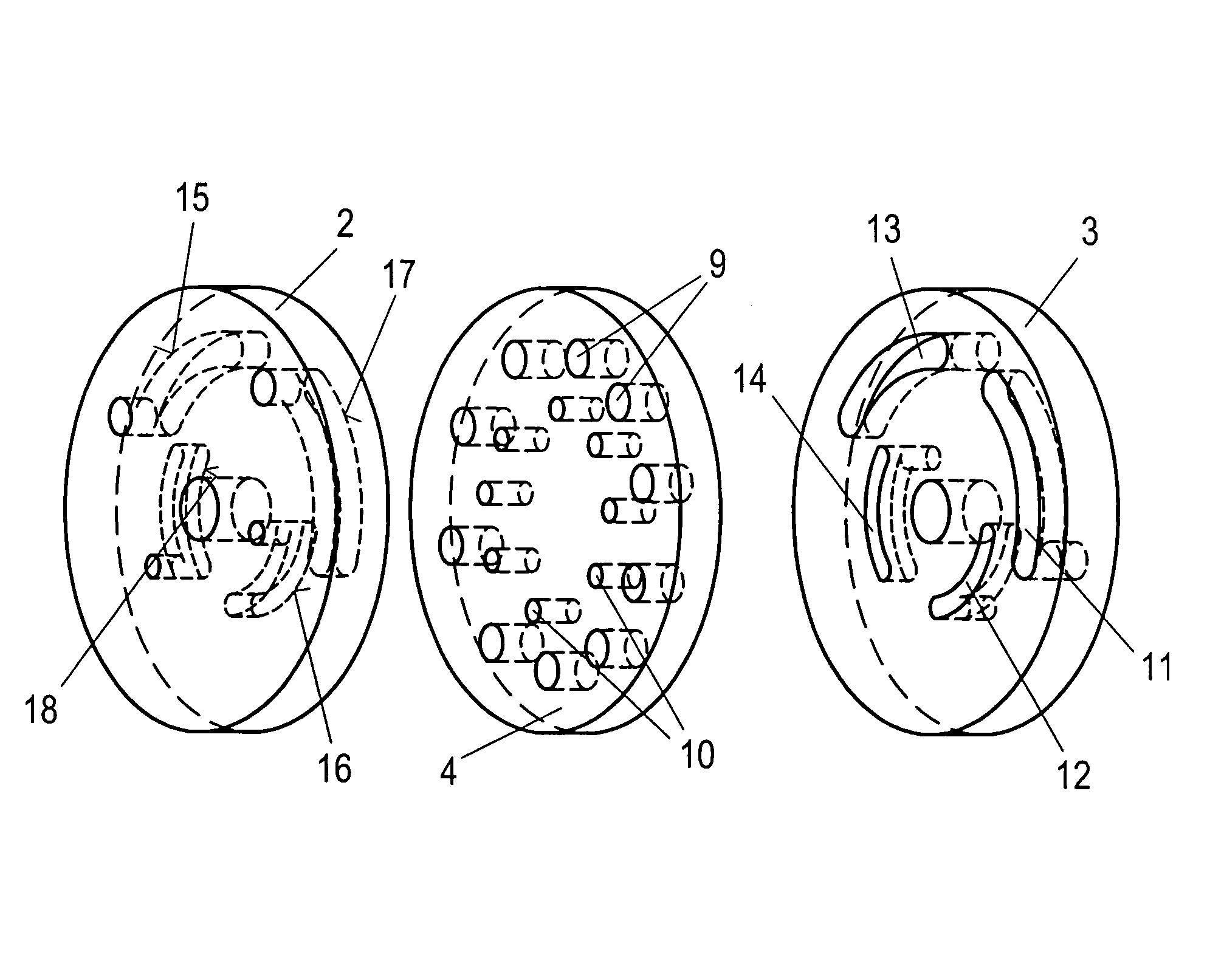
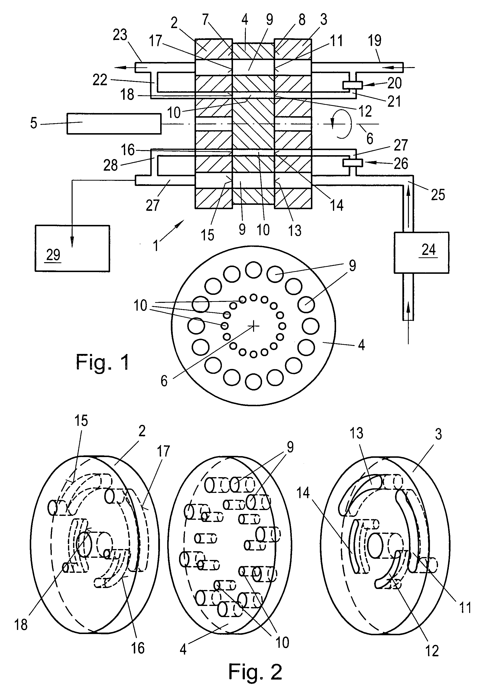
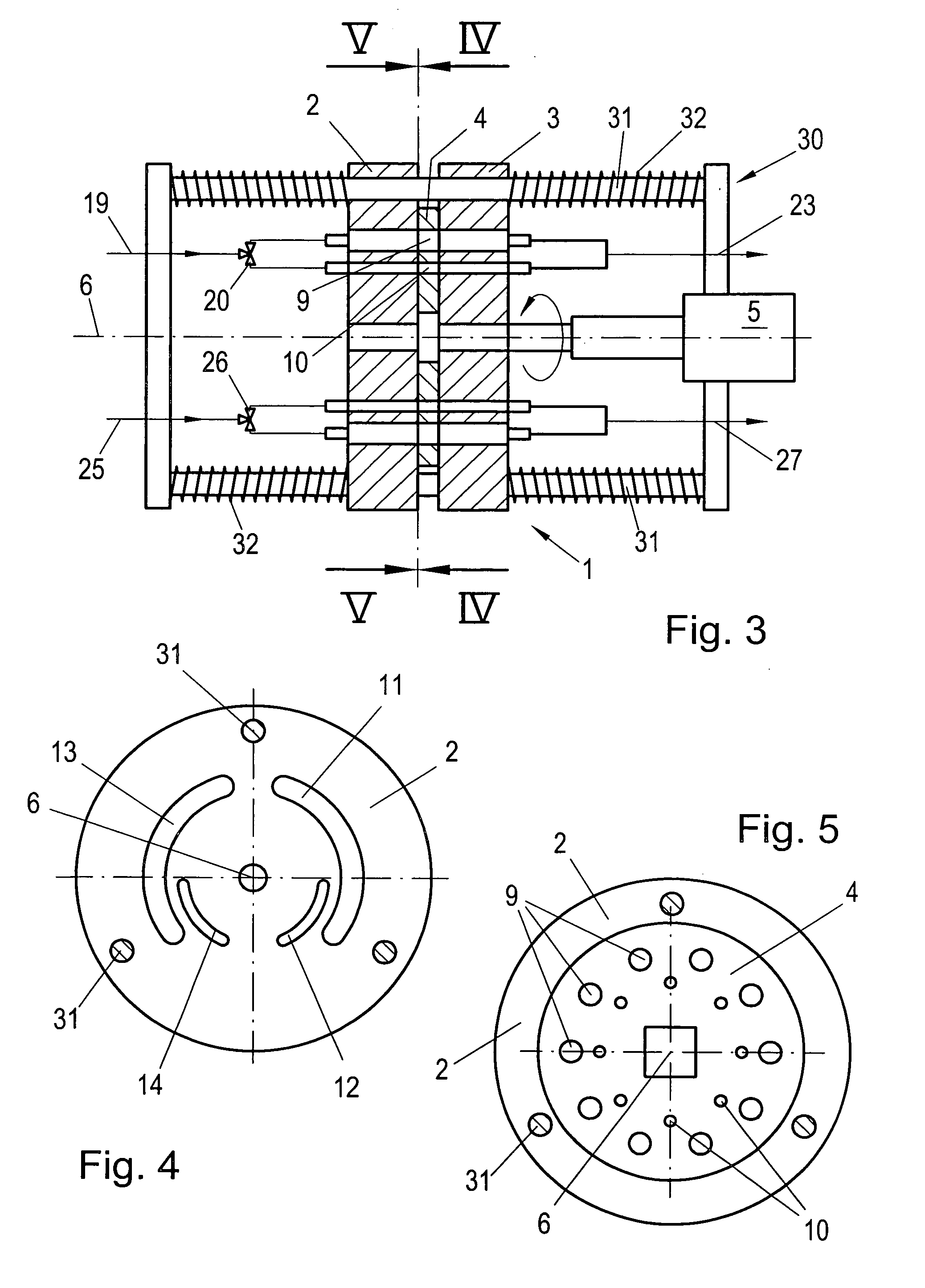
[0022]The rotating disc diluter 1 according to FIG. 1 has a rotatable rotary element 4 between two stationary elements 2, 3, which by means of a stepper motor 5 is rotatable around its axis 6, and is provided with discrete transfer volumes 9, 10 which are surface-accessible from both sides 7, 8. As is especially also to be seen from the side plan view, shown separately at the bottom in FIG. 1, of the rotary element 4 (in the direction of the axis 6), two separate rows of transfer volumes (9 on the one hand and 10 on the other hand) are provided in this case, which, during rotation of the rotary element 4 around its axis 6, on two different paths of movement glide in each case alternately over feed and discharge ports 11 to 18 in the sides 7, 8 of the stationary elements 2, 3 which interact with the rotary element 4 with sealing effect.

[0023]An undiluted flow fluid (gaseous or even liquid, for example particle-laden exhaust gas of an internal combustion engine) is fed via a line 19. ...


PUM


Abstract

A rotating disc diluter (1) has a rotatable rotary element (4) which carries surface-accessible transfer volumes (9, 10) which along their common path of movement alternately glide over feed and discharge ports (11-18) for an undiluted fluid flow on the one hand and for a dilution fluid flow on the other hand. For the simple widening of the usable dilution rate range, the rotary element (4) has at least two rows of transfer volumes (9, 10) on different paths of movement, the associated feed ports (11-14) of which for the undiluted fluid flow and/or for the dilution fluid flow can be separately controlled.

Description

BACKGROUND OF THE INVENTION[0001]1. Field of the Invention[0002]The invention relates to a rotating disc diluter for fluid flows, with a rotatable rotary element which has surface-accessible discrete transfer volumes which along their common path of movement alternately glide over feed and discharge ports for the undiluted fluid flow on the one hand and for a dilution fluid flow on the other hand.[0003]2. The Prior Art[0004]Such arrangements, which are also referred to as carrousel diluters, for example are known from “Journal of Aerosol Science, 1997, Vol. 28, Nr. 6, pages 1049 to 1055” and are mostly used for taking measurements of liquid or gaseous fluid flows and especially when for the better utilization of limited measuring ranges of the measuring devices defined pre-dilutions are required in a dilution rate range which is as large as possible. A basic block of the arrangement which is known from the mentioned literature reference has two connecting passages; one for the undil...

Claims


Application Information

Patent Timeline
IPC IPC(8): F16K11/065B01L99/00
CPCF16K11/074Y10T137/86493Y10T137/86558
Inventor BERGMANN, ALEXANDERPONGRATZ, HELMUT
Owner AVL LIST GMBH
Why Eureka
Try Eureka