Illuminated skeet target

a skeet target and lighted technology, applied in the field of lighted skeet targets, can solve the problems of not being used to illuminate targets that fly through the air, no value or benefit from tracing the fired ammunition,

Active Publication Date: 2013-05-07
TAYLOR EUGENE
View PDF26 Cites 7 Cited by
  • Summary
  • Abstract
  • Description
  • Claims
  • Application Information

AI Technical Summary

Benefits of technology

[0009]One aspect of the present invention may be to provide for an illuminated skeet target comprising a body formed from a sulfur binder, fly ash and calcium carbonate; and a raised ridge extending from an ou

Problems solved by technology

Under such circumstances, tracing the fired ammunition is not of any value or benefit.
However, while it has been used to illumina

Method used


Image

  • Illuminated skeet target
  • Illuminated skeet target
  • Illuminated skeet target

Examples


Embodiment Construction

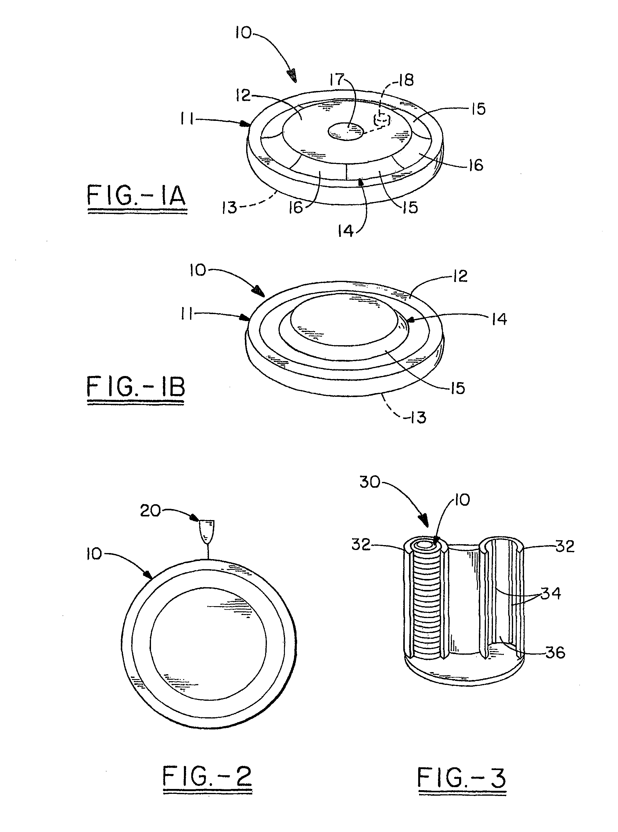
[0025]It is a feature of the present invention to provide an illuminated skeet target 10 so that a sportsman may skeet shoot in the evening and night, or any other time when ambient lighting is not sufficient to see the skeet target 10. For the purposes of the following discussion, the term “skeet target” is defined herein as any skeet, clay pigeon, or other suitable target that can be launched in the air for the purpose of being shot at with a projectile, such as a bullet from a gun. Furthermore, the teachings of U.S. Pat. Nos. 4,124,550; 6,085,427; and 7,174,904 are incorporated herein by reference. An illuminated skeet target 10 comprises a disc-shaped body 11 having an upper surface 12 that is opposite a lower surface 13, as shown in FIGS. 1A-B. Although the target 10 is shown as being substantially disc-shaped, it may be formed as any shape suitable for launching into the air. In one aspect, the skeet target 10 may be shaped similar to that of a conventional clay pigeon. The sk...


PUM


Abstract

An illuminated skeet target comprises a substantially disc-shaped body that is suitable for launching via a trap or other launching device. The skeet target contains at least two reagents that undergo a chemiluminescent reaction and give off light when combined so that the skeet target can be illuminated and identified when ambient lighting conditions are insufficient.

Description

CROSS-REFERENCE TO RELATED APPLICATIONS[0001]This application is a continuation-in-part of U.S. patent application Ser. No. 12 / 154,953, filed May 28, 2008 now abandoned, which claims priority of U.S. Provisional Patent Application No. 60 / 932,055, filed May 29, 2007.TECHNICAL FIELD[0002]This invention relates to a luminescent or lighted skeet target and, more specifically, to a skeet target that is illuminated by chemiluminescence. Such a skeet target is better illuminated for shooting during dusk or dark conditions.BACKGROUND OF THE INVENTION[0003]New twists on traditional sports have sparked a resurgence in their participation. For example, a twist on bowling is the use of luminescent pins instituted in alleys for “glow-in-the-dark” games. Another example is the indoor “glow-in-the-dark” miniature golf courses that utilize a means to illuminate golf balls and the associated holes or cups. Similar efforts have been made to adapt activities performed during the day-time, more suitabl...

Claims


Application Information

Patent Timeline
IPC IPC(8): F41J9/16
CPCF41J9/165
Inventor TAYLOR, EUGENE
Owner TAYLOR EUGENE
Why Eureka
Try Eureka