Impact absorption facility for road

a technology for absorption facilities and roads, applied in roadway safety arrangements, roads, construction, etc., can solve the problems of increasing casualties, increasing the risk of accidents, so as to reduce the impact, minimize the damage of vehicles and passengers, and minimize the damage. , the effect of reducing the impa

Active Publication Date: 2013-05-07
GEUM SUNG IND
View PDF16 Cites 16 Cited by
  • Summary
  • Abstract
  • Description
  • Claims
  • Application Information

AI Technical Summary

Benefits of technology

[0012]Accordingly, it is an object of the present invention to provide an impact absorption facility for road which has ultraviolet ray block, dust attachment prevention, light reflection and nightglow and makes it possible to absorb and release the impacts that the vehicle receives when the vehicle collides with the impact absorption facility with an elastic member such as rubber or synthetic resin which is capable of absorbing the impacts. It is possible to decrease the speed of the vehicle at the time of vehicle collision while guiding the vehicle to run an intended running direction, so the driver can reenter the normal running way while holding the handle.
[0013]It is another object of the present invention to provide an impact absorption facility for road which can protect ramp inlets and outlets, entrance of tunnel or underground way, pillars, faith silk or something and decreasing the impacts when a vehicle collides with an impact absorption facility installed at a highway ramp or junction and preventing a vehicle from entering a center line and getting out of the road for thereby minimizing a huge accident and the damages of vehicles and passengers.
[0014]It is further another object of the present invention to provide an impact absorption facility for road which makes it possible to easily manage by fabricating the structure of an impact absorption facility for road in an assembling type for thereby easily exchanging the damaged elements when the vehicle is damaged by accidents. A LED solar cell which automatically flashes and has a solar cell battery is installed in the upper side of the pillar of the impact absorption facility for thereby preventing the accidents with the help of the flashing of the LED lamp at night.

Problems solved by technology

Since a conventional impact absorption facility is formed of a protective wall, a protective mount, a guide rail each made of a waste tire, a steel material or concrete, the friction force increases at the time when a vehicle collides, so a vehicle is damaged or broken, leading to casualties.
As vehicle collision accidents increase year after year, a lot of impact absorption facilities installed in a sharp curve and a mountain area are damaged.
In particular, since it is made of a metallic material or a concrete block, casualties might increase when a vehicle collides, and a lot of budget is needed so as to maintain the damaged impact absorption facility.
However t is impossible to actually decrease the speed of the vehicle due to the rotational force of the impact absorption member such as a manmade absorption material like waste tires and Styrofoam.
In this case, a secondary accident may occur as the vehicle collides with another running vehicle of another running lane, which might cause a huge accident.
The impact absorption facility embedded in the centerline or the road side has a complicated construction which might lead to increasing the unit cost, and the assembling time might increase due to a lot of elements to be assembled at site.
In particular, when it is hard to see the front side vehicles in curved roads or uphill roads, the vehicle collides and keeps running without deceleration, from which a huge accident can occur.
So, the vehicle that collided might collapse and might get popped out of the running road.
Since the rotational speed of the impact absorption body is in proportion to the impact speed in the course of the impact of the vehicle, it is actually hard to prevent safety accidents due to the deceleration of a vehicle, so that a secondary traffic accident such as a collapse or a road escape can occur.

Method used


Image

  • Impact absorption facility for road
  • Impact absorption facility for road
  • Impact absorption facility for road

Examples


Embodiment Construction

[0106]The preferred embodiments of the present invention will be described with reference to the accompanying drawings.

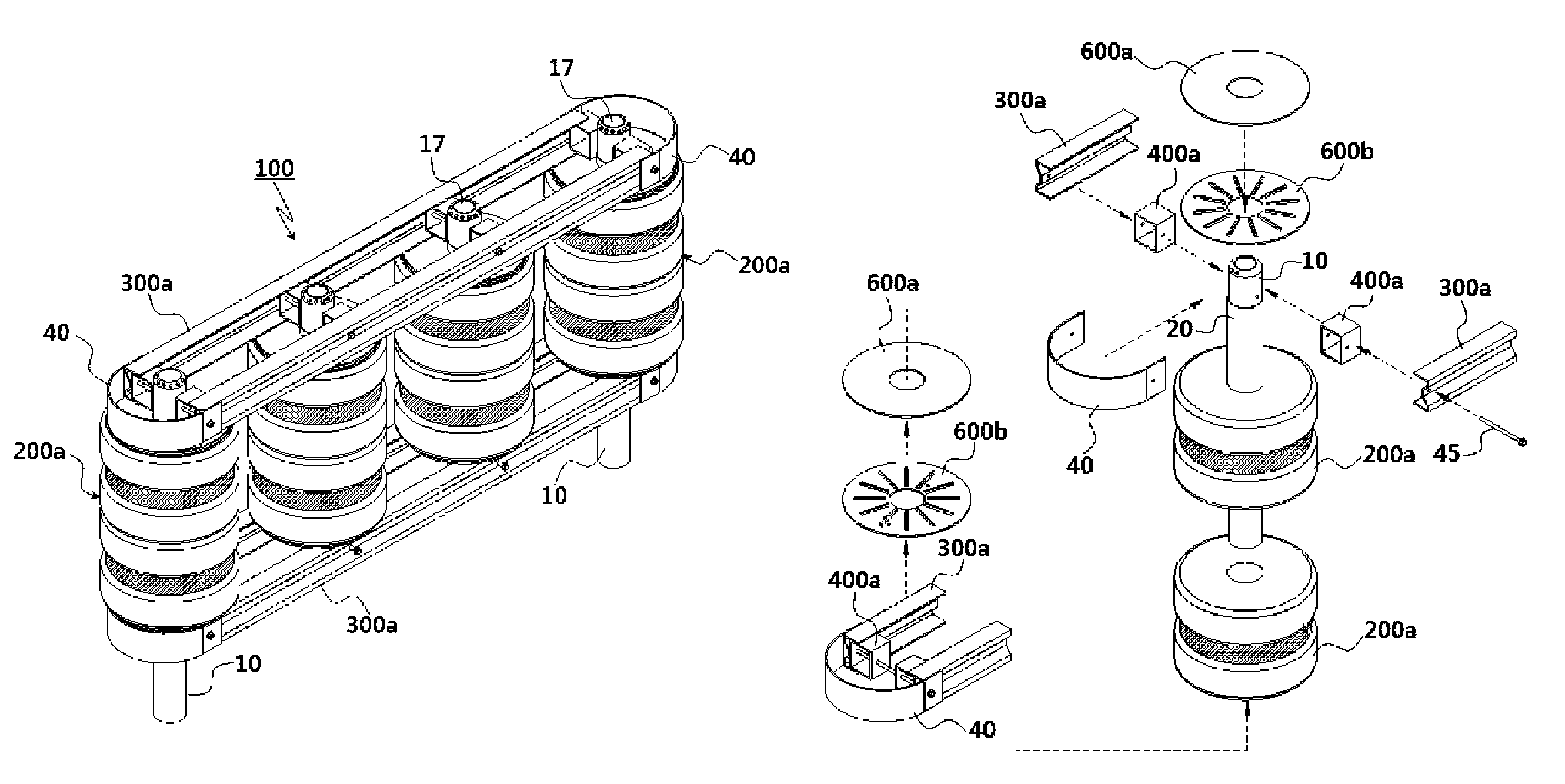
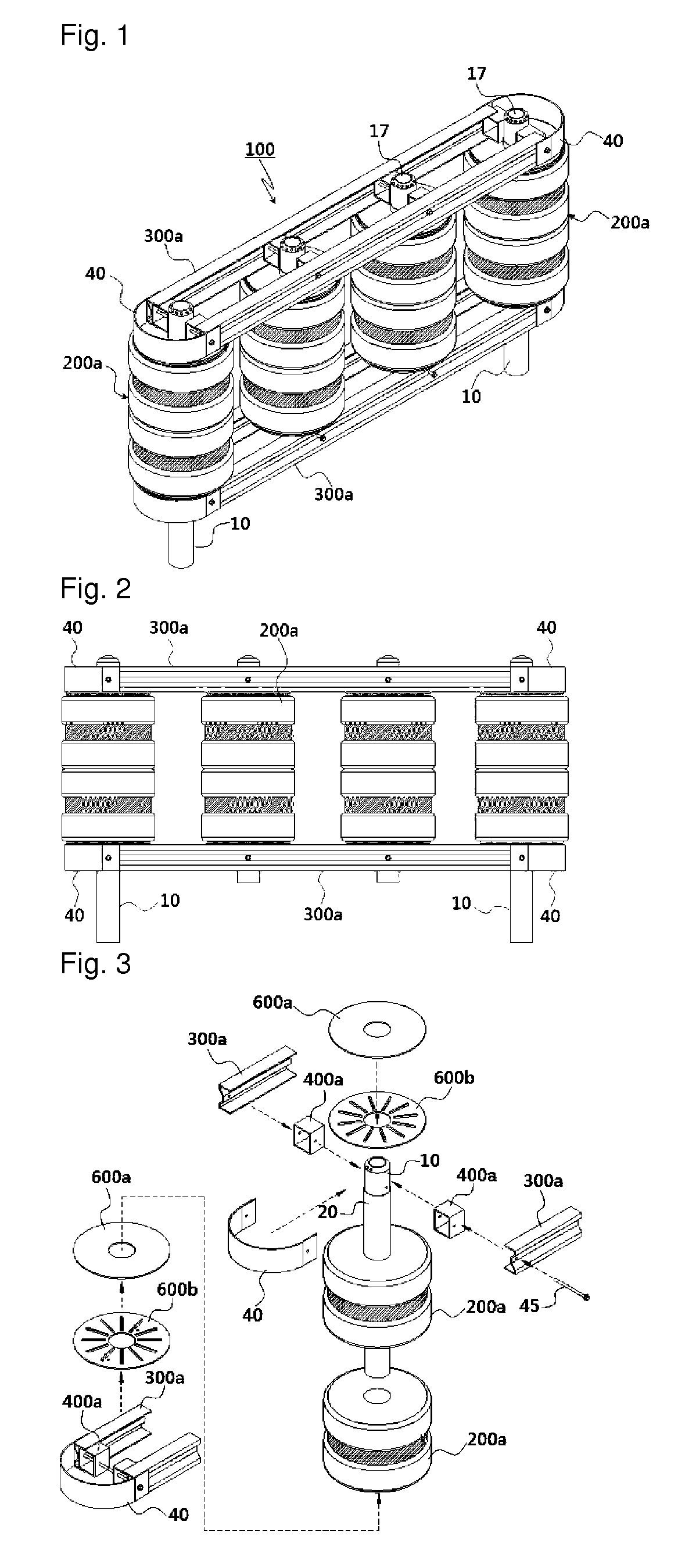
[0107]As shown in FIGS. 1 to 3, the present invention is basically directed to an impact absorption facility for road which is installed in a centerline of a road or road sides for thereby absorbing and distributing the impacts occurring when a vehicle collides.

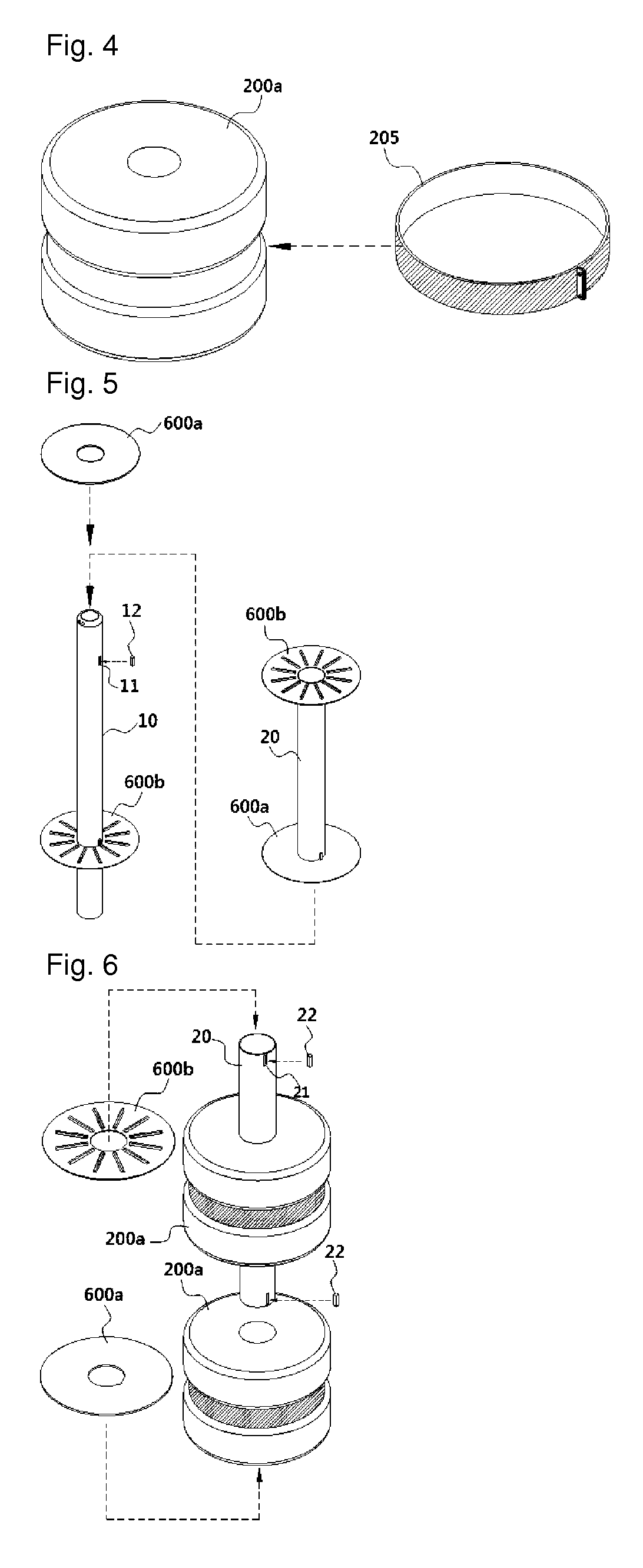
[0108]The present invention includes a column-shaped pile 10 fixedly embedded in a centerline of a road or road sides at regular intervals, and a rotation support pipe 20 which is engaged with the help of the pipe 10 and is rotatable.

[0109]The rotation support pipe 20 includes an engaging member 201 which is engaged to its outer side and is rotatable, a plurality of cushioning members 200a each formed in a cylindrical shape and made from integral elastic rubber material in its inner and outer sides, with a high luminance reflection band 205 being engaged to each cushioning member, and a plurality of safety ra...


PUM


Abstract

An impact absorption facility for road makes it possible to protect a road center, a road side, a road ramp, an entering side of a tunnel or an underground road, pillars, faith silk or others and to absorb the impact of vehicle collided and to decelerate during a collision by decreasing the impacts occurring due to the impact of a vehicle by installing the impact absorption facility even in a highway ramp, and it is possible to prevent a vehicle from entering an opposite road lane or going out of a road for thereby allowing the vehicle to run on a normal road and to return to a road. A traffic accident can be effectively prevented with the help of a lighting lamp or a reflection lamp when a vehicle approaches the impact absorption facility when a driver drives at night with sleepiness.

Description

BACKGROUND OF THE INVENTION[0001]The present invention relates to an impact absorption facility for road, and in particular to an impact absorption facility for road which makes it possible to protect a road center, a road side, a road ramp, an entering side of a tunnel or an underground road, pillars, faith silk or others and to absorb the impact of vehicle collided and to decelerate during a collision by decreasing the impacts occurring due to the impact of a vehicle by installing the impact absorption facility even in a highway ramp, and it is possible to prevent a vehicle from entering an opposite road lane or going out of a road for thereby allowing the vehicle to run on a normal road and to return to a road. A traffic accident can be effectively prevented with the help of a lighting lamp or a reflection lamp when a vehicle approaches the impact absorption facility when a driver drives at night with sleepiness.[0002]Since a conventional impact absorption facility is formed of a...

Claims


Application Information

Patent Timeline
Patent Type & Authority Patents(United States)
IPC IPC(8): E01F15/02E01F15/08E01F9/619
CPCE01F15/003E01F15/0492E01F15/025
Inventor CHAE, JONG-SUL
Owner GEUM SUNG IND
Why Eureka
Try Eureka