Clavicle nail with locking end cap

a clavicle and end cap technology, applied in the field of surgical procedures, to achieve the effect of preventing physiological damage, capturing and retaining, and improving therefore the overall success of fracture repair

Active Publication Date: 2013-05-07
ARTHREX
View PDF7 Cites 94 Cited by
  • Summary
  • Abstract
  • Description
  • Claims
  • Application Information

AI Technical Summary

Benefits of technology

[0007]The clavicular nail may be provided in incremental diameters between about 1.5 mm to about 3.5 mm. The size chosen is based upon the internal diameter of the patient's intramedullary canal. The nail is designed with a plurality of circumferential grooves or indentations on one end which will mate with the nail receptor of the end cap. The clavicular nail receptor (locking mechanism) of the end cap is designed with a body (having a cylindrical configuration, for example) provided with a cavity extending partially therethrough. The cavity receives an end of the fracture nail and securely retains the captured fracture nail. To aid in the capturing and retention of the fracture nail, the body of the clavicular nail receptor is provided with a plurality of slots that extend about parallel to the longitudinal axis of the end cap. The slots allow the body of the end cap to “spring” open or flare open when the fracture nail is pressed into the open end of the end cap. After the fracture nail is advanced into the cavity of the end cap, the end cap returns to the initial diameter, and securely captures the fracture nail within one of the grooves in the fracture nail. By providing the slots within the body of the end cap, the nail receptor prohibits any lateral and / or medial movement of the captured fracture nail and prevents both lateral and medial migration of the nail, improving therefore the overall success of the fracture repair and preventing possible physiological damage from an internal loose body.

Problems solved by technology

Pin fixation within the medullary canal of a broken clavicle is often associated, however, with undesirable migration of the pin within the medullary canal.

Method used


Image

  • Clavicle nail with locking end cap
  • Clavicle nail with locking end cap
  • Clavicle nail with locking end cap

Examples


Embodiment Construction

[0021]In the following detailed description, reference is made to a specific embodiment in which the invention may be practiced. This embodiment is described with sufficient detail to enable those skilled in the art to practice the invention and it is to be understood that other embodiments may be employed, and that structural and logical changes may be made without departing from the spirit or scope of the present invention.

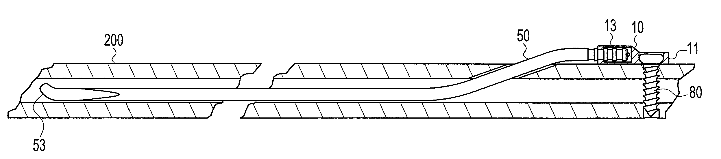
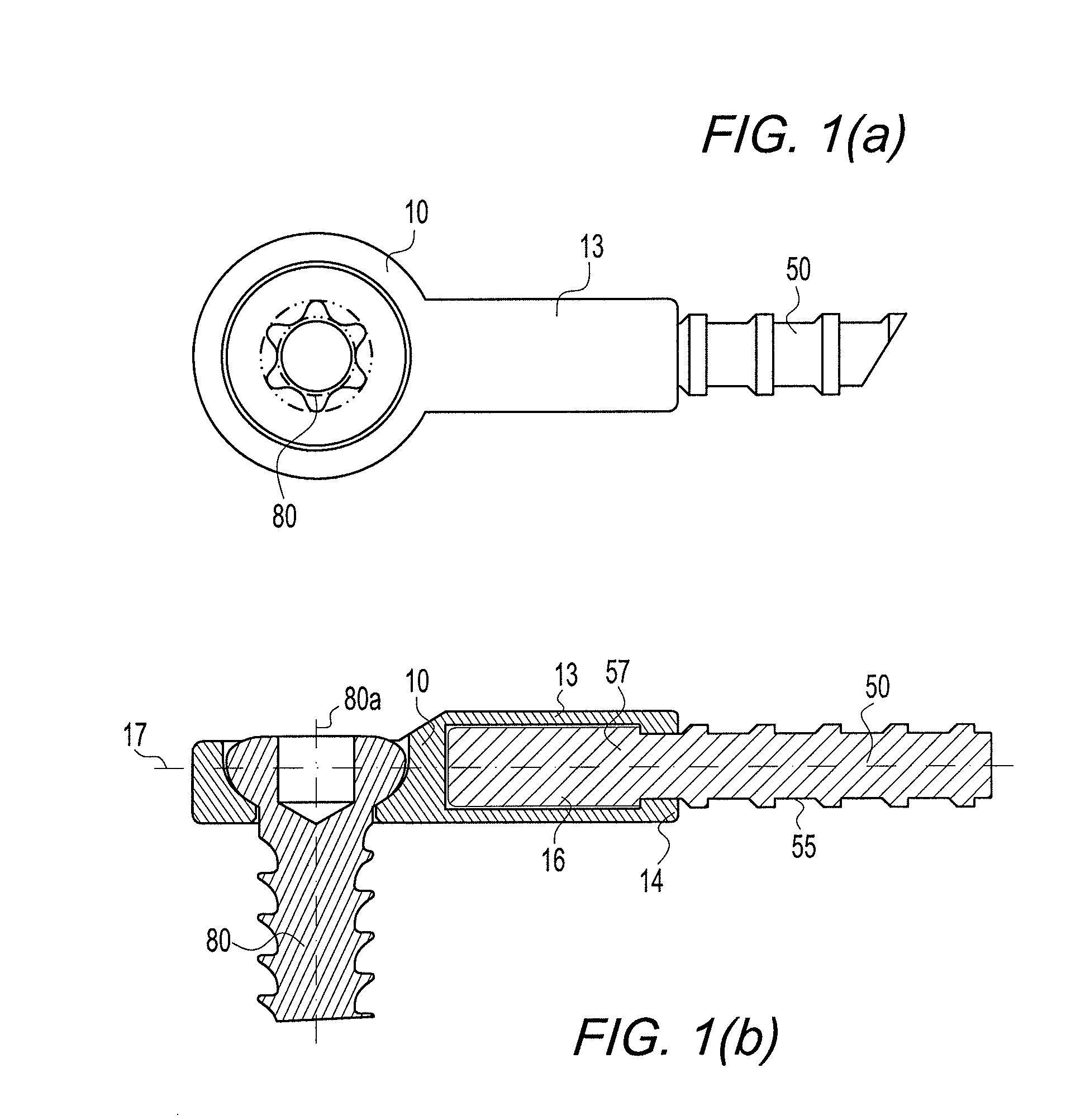
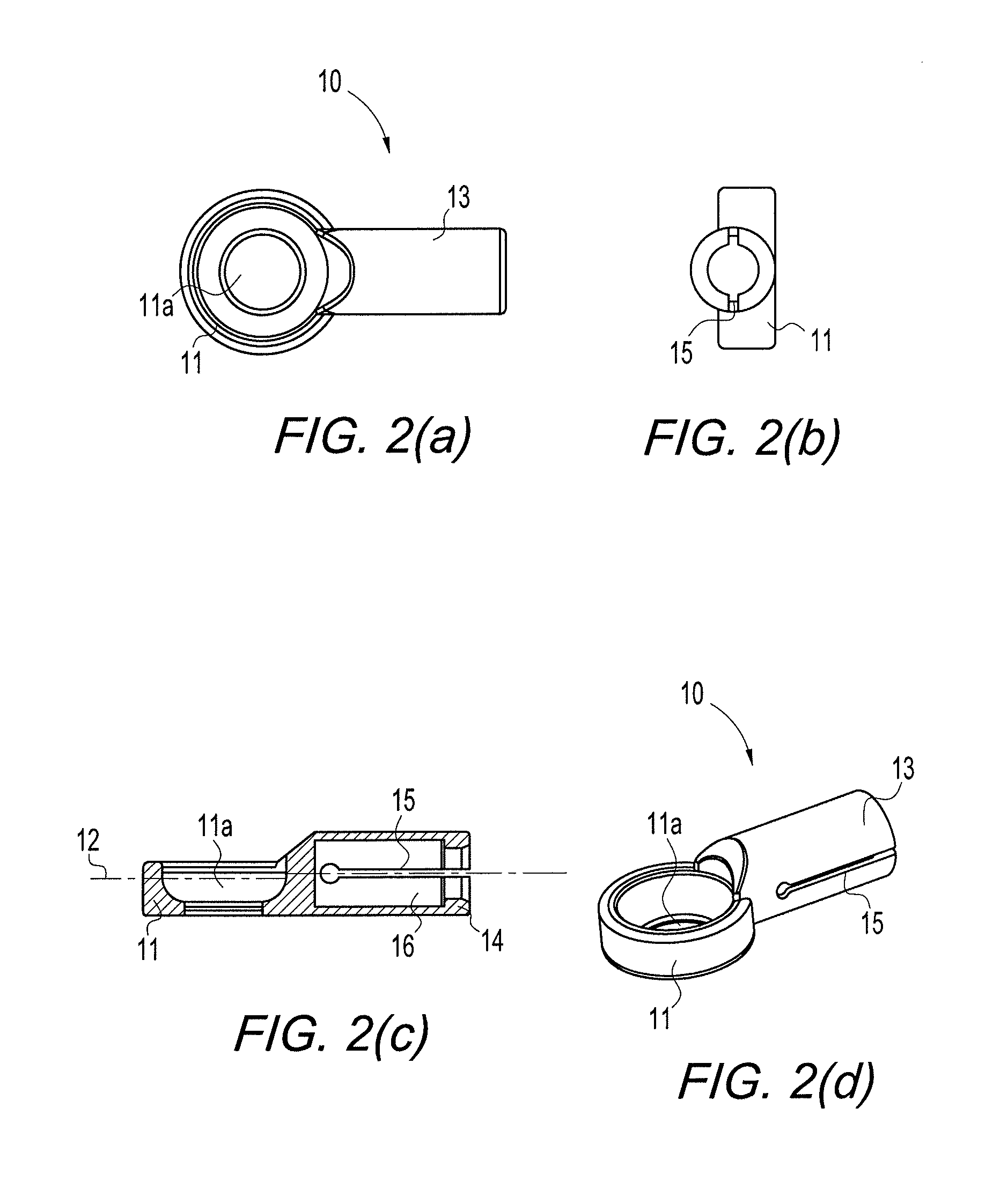
[0022]The present invention provides a fixation assembly for fixing clavicle (collarbone) fractures. The clavicle fixation assembly of the present invention includes a clavicle end cap (terminal button or terminal cap) configured to securely capture and retain a fracture nail. The end cap is provided with a retaining device and a clavicular nail receptor.

[0023]The retaining device is provided with a through opening to allow a fixation device (for example, a screw or fastener) to be inserted through the opening and into the broken clavicle to secure the clavicle ...


PUM


Abstract

A device for reducing migration of a pin of an intramedullary fixation device, especially to reduce migration of a clavicle pin introduced in the medullary canal of the clavicle to fix a fractured clavicle bone. A clavicle nail with a curved tip is inserted within the medullary canal of the clavicle. The back end of the nail that extends out of the clavicle is provided with indentations or grooves. The back end of the nail is received in a hollow cavity of a cap, which locks onto the indentations or grooves of the nail. A screw is placed through an eyelet of the cap and turned into the clavicle to secure the cap to the clavicle. As a result, the nail is fixed within the medullary canal and undesirable migration of the pin within the medullary canal is reduced.

Description

CROSS-REFERENCE TO RELATED APPLICATIONS[0001]This application claims the benefit of U.S. Provisional Application No. 61 / 168,125, filed on Apr. 9, 2009, the entire disclosure of which is incorporated by reference herein.FIELD OF THE INVENTION[0002]The present invention relates to methods and apparatus for surgical procedures and, more particularly, to a locking clavicular device for securing a fracture nail in the collarbone.BACKGROUND OF THE INVENTION[0003]Clavicle fractures (also known as broken collarbones) are a common injury. For a long time, the treatment of a clavicle fracture has been simply conservative, non-surgical care (non-operative treatment). Over the last few years, however, various devices such as plates, screws and pins have been developed to aid in the operative treatment of clavicle fractures, reducing the chronic pain, weakness and high nonunion rate typically associated with the non-operative treatment of the clavicle fractures.[0004]For example, clavicle plates...

Claims


Application Information

Patent Timeline
Patent Type & Authority Patents(United States)
IPC IPC(8): A61B17/86A61F2/08
CPCA61B17/7241A61B17/7291
Inventor DOUGHERTY, CHRISTOPHER P.GALLEN, KEVIN J.SHULER, DONALD K.
Owner ARTHREX
Why Eureka
Try Eureka