System and method of determining object pose

a technology of object pose and system, applied in the field of robot vision based systems, can solve the problems of inability to obtain models from original equipment manufacturers, lack of sharp or high contrast features of models, and inability to clearly distinguish objects, etc., and achieve the effect of increasing the efficiency of object pose determination

Active Publication Date: 2013-05-07
ROBOTICVISIONTECH INC
View PDF192 Cites 43 Cited by
  • Summary
  • Abstract
  • Description
  • Claims
  • Application Information

AI Technical Summary

Problems solved by technology

However, some objects do not possess clear, visible and / or readily identifiable geometric features, such as sharp, high contrast edges, contours, holes, etc.
For example, car body panels such as roofs and hood panels are typically flat and lack sharp or high contrast features.
While computer aided design (CAD) models of the objects may exist, these models are typically difficult to obtain from original equipment manufacturers (OEMs) due to confidentiality concerns.
Independently developing models is time consuming and expensive.
A priori measurements of the geometry of these objects are typically lengthy operations and require specialized equipment, such as coordinate measurement machines, or complex and expensive secondary scanning devices that require a high level of expertise to operate.
A separate challenge is related to the problem of determining the pose of such objects.
Given the sparseness or lack of well-constrained visual features such as holes, corners, and fillets on many objects of interest, as well as the typically large size of such objects, the information from one region of the object is often insufficient to determine the overall pose of the object, at least to a sufficient degree of accuracy / repeatability for the required number of degrees of freedom or constraint.
However, the above U.S. patents are deficient in at least two major areas.
First, a priori modeling information is required for the surface geometry of the target objects which, as explained above, may be difficult and / or expensive to obtain.
Secondly, there are no practical methods for using a relatively small surface region of the object to determine overall object pose, unless that small surface region has unique features and / or characteristics which allow precise determination of pose.
For example, determining the pose of an automobile hood based upon a small region is not practical because the hood is typically a relatively flat and smooth surface with no readily discernible unique features and / or characteristics (in at least a small localized area of the hood).

Method used


Image

  • System and method of determining object pose
  • System and method of determining object pose
  • System and method of determining object pose

Examples


Embodiment Construction

[0023]In the following description, certain specific details are set forth in order to provide a thorough understanding of various embodiments. However, one skilled in the art will understand that the embodiments may be practiced without these details. In other instances, well known structures associated with robotic systems have not been shown or described in detail to avoid unnecessarily obscuring descriptions of the embodiments.

[0024]Unless the context requires otherwise, throughout the specification and claims which follow, the word “comprise” and variations thereof, such as “comprises” and “comprising,” are to be construed in an open sense, that is as “including, but not limited to.”

[0025]The headings provided herein are for convenience only and do not interpret the scope or meaning of the claimed embodiments.

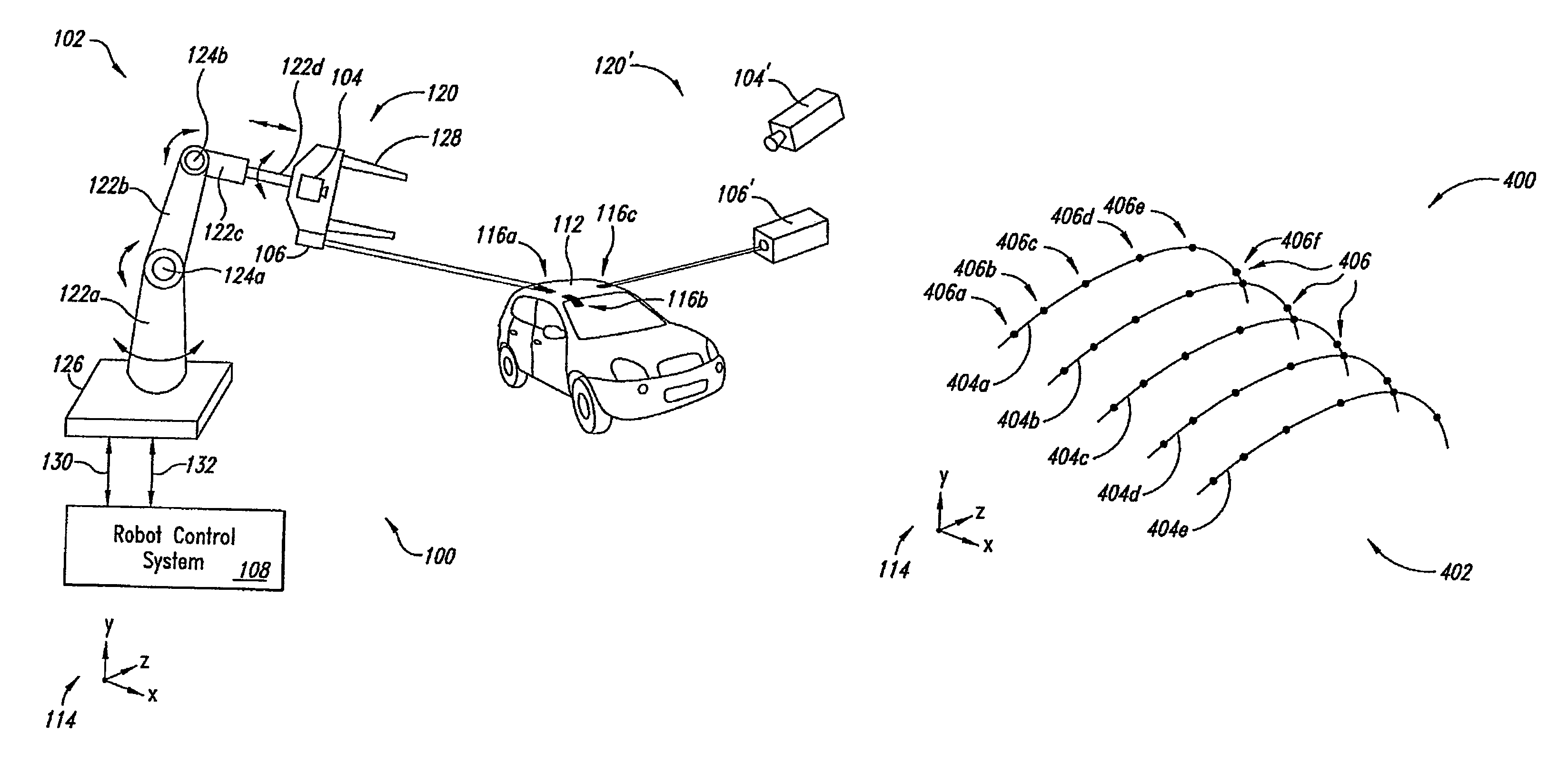
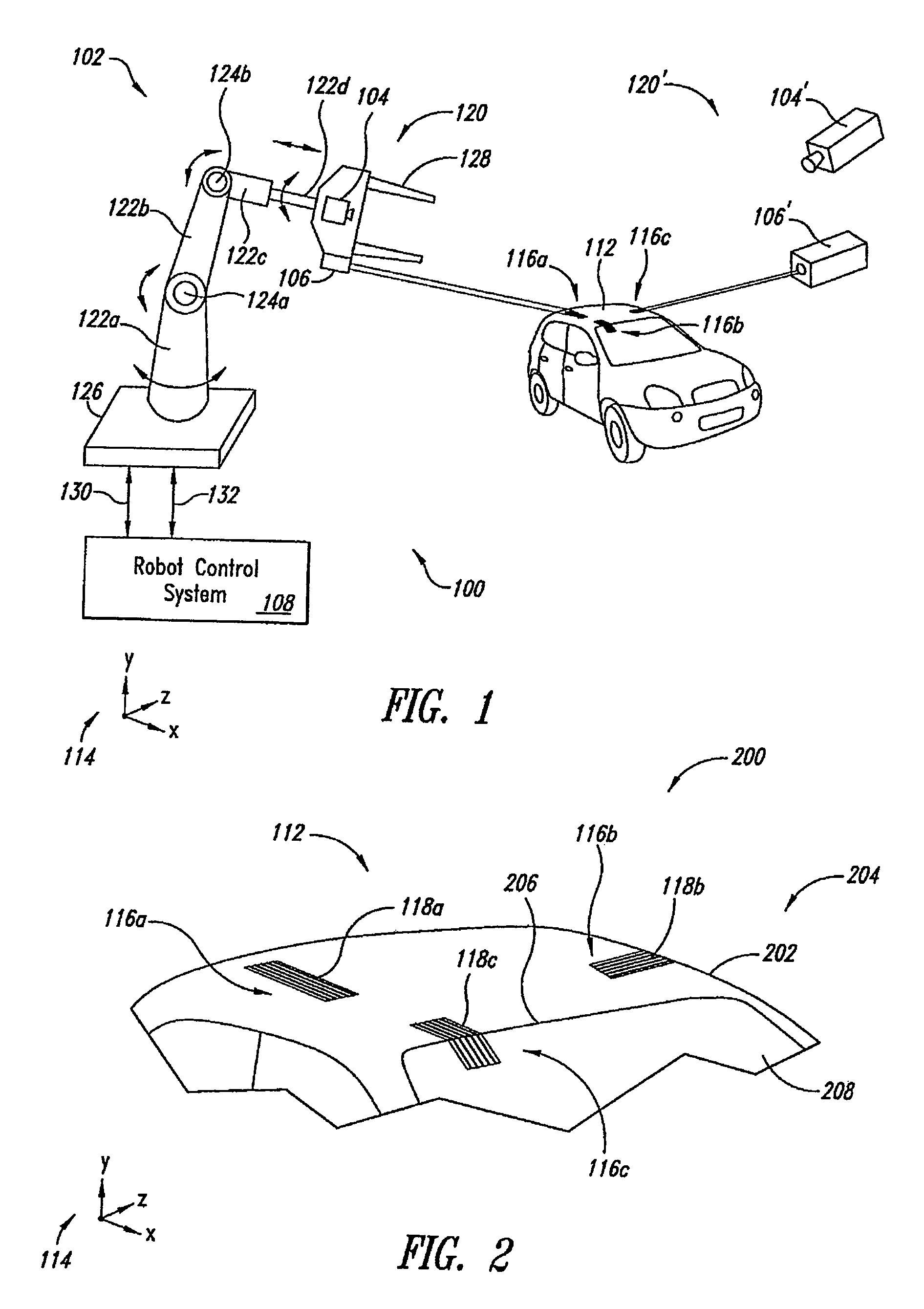
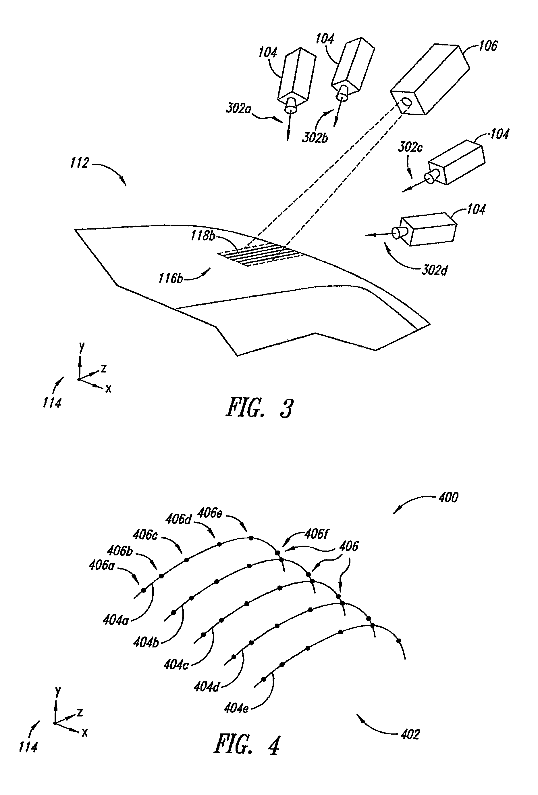
[0026]Overview of the Object Pose Determination System

[0027]Images of one or more local surfaces are captured to determine a pose of an object of interest. Image capture o...


PUM


Abstract

Briefly described, one embodiment determines pose of an object of interest at a run time by capturing a first image of a first structured light pattern projected onto a first local surface of the object of interest; determining a first run-time data set from the captured first image, wherein the first run-time data set corresponds to information determined from the first structured light pattern projected onto the first local surface; comparing the determined first run-time data set and a corresponding first reference data set, the first reference data set corresponding to an ideal pose of the first local surface on an ideally posed reference object; and determining at least one first degree of constraint that defines a first partial pose of the first local surface, the at least one first degree of constraint based upon the comparison of the first run-time data set with the corresponding first reference data set.

Description

CROSS-REFERENCE TO RELATED APPLICATION[0001]This application claims the benefit under 35 U.S.C. §119(e) of U.S. Provisional Patent Application No. 60 / 845,932 filed Sep. 19, 2006, where this provisional application is incorporated herein by reference in its entirety.BACKGROUND[0002]1. Field of the Invention[0003]This disclosure generally relates to robotic systems and, more particularly, to robotic vision based systems operable to determine object pose (location and orientation) in three dimensional space.[0004]2. Description of the Related Art[0005]It is often necessary or desirable to determine object pose (i.e., position and orientation) for objects in controlling robotic systems. However, some objects do not possess clear, visible and / or readily identifiable geometric features, such as sharp, high contrast edges, contours, holes, etc. For example, car body panels such as roofs and hood panels are typically flat and lack sharp or high contrast features.[0006]While computer aided d...

Claims


Application Information

Patent Timeline
Patent Type & Authority Patents(United States)
IPC IPC(8): G06K9/00
CPCG01B11/25G01S17/875
Inventor BOCA, REMUS F.PESCARU, SIMONA LILIANABEIS, JEFFREY SCOTTHABIBI, BABAK
Owner ROBOTICVISIONTECH INC
Why Eureka
Try Eureka