Wrap spring clutch coupling with quick release feature

a technology of clutch coupling and wrap spring, which is applied in the direction of clutches, friction clutches, clutches, etc., to achieve the effect of facilitating the quick release of the wrap spring and reducing the difference in rotational speed between the hubs

Active Publication Date: 2013-05-14
INERTIA DYNAMICS
View PDF11 Cites 0 Cited by
  • Summary
  • Abstract
  • Description
  • Claims
  • Application Information

AI Technical Summary

Benefits of technology

[0009]A rotational coupling in accordance with the present invention represents an improvement relative to conventional rotational couplings and, in particular, conventional wrap spring clutches. By providing a mechanism that urges the wrap spring away from the hub on which the spring wraps down, the inventive clutch facilitates quick release of the wrap spring even in applications in which the difference in rotational speed among the hubs is low. As a result, the inventive clutch can be used in additional applications previously considered unsuitable for a wrap spring clutch.

Problems solved by technology

As a result, the inventive clutch can be used in additional applications previously considered unsuitable for a wrap spring clutch.

Method used


Image

  • Wrap spring clutch coupling with quick release feature
  • Wrap spring clutch coupling with quick release feature
  • Wrap spring clutch coupling with quick release feature

Examples


Embodiment Construction

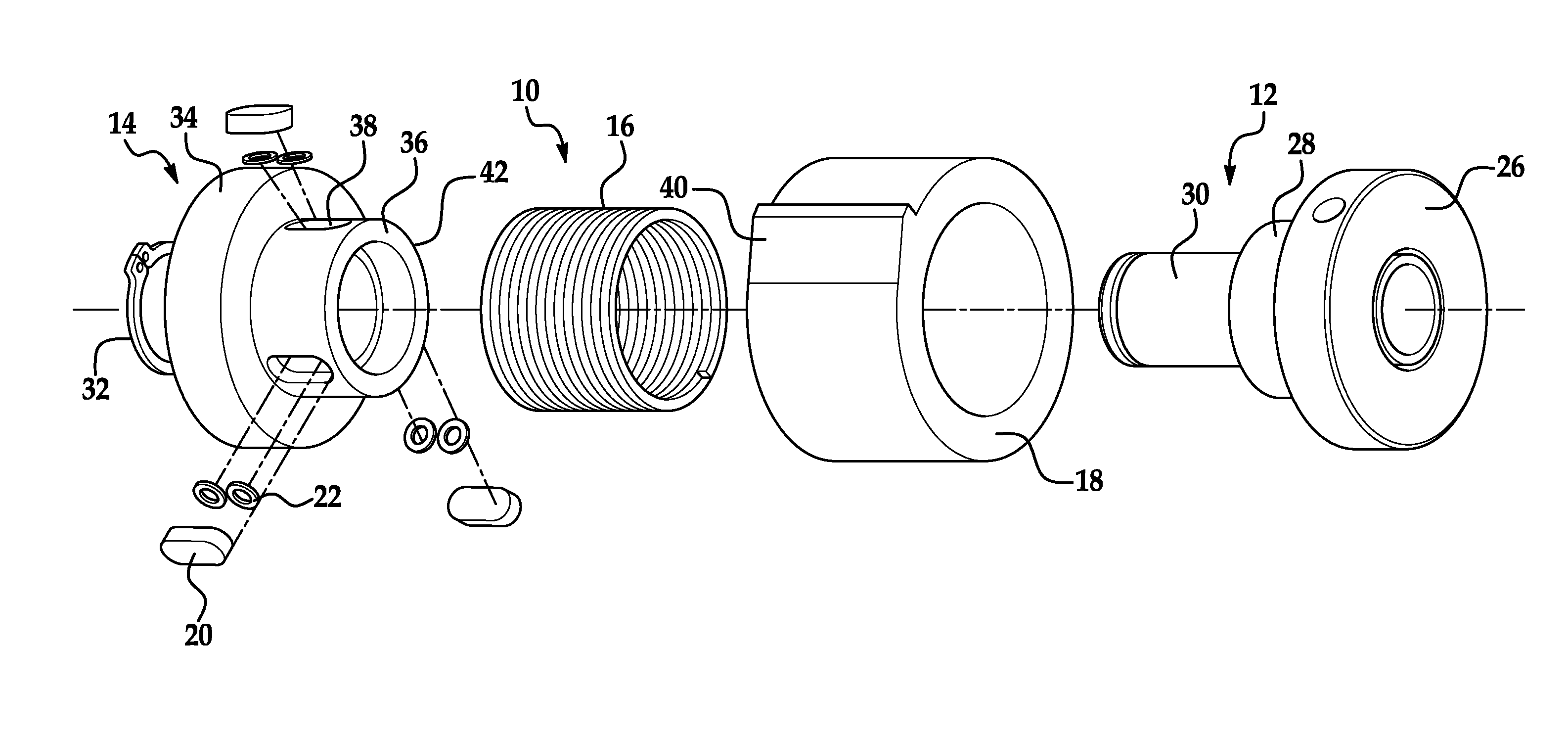
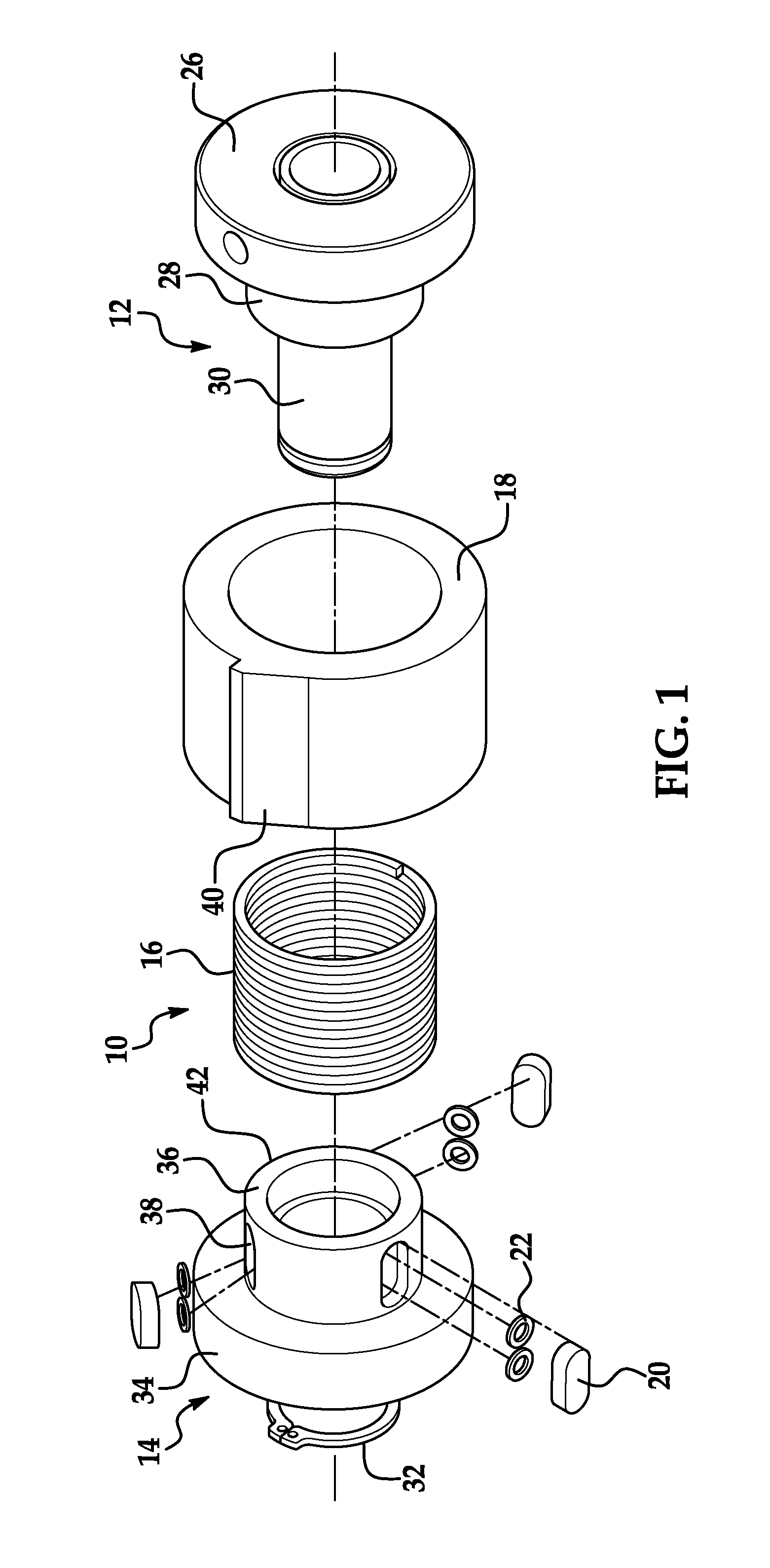
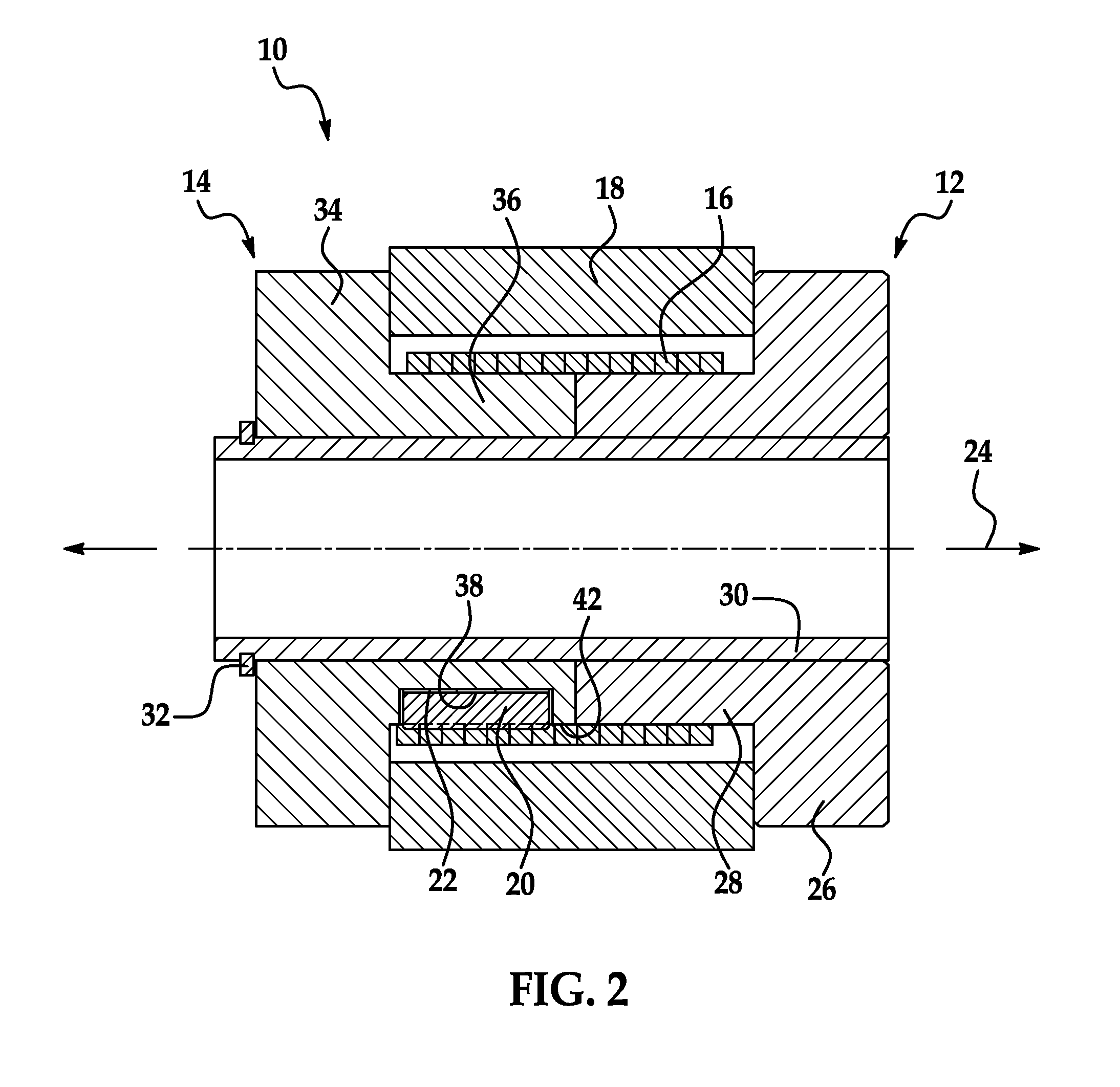
[0013]Referring now to the drawings wherein like reference numerals are used to identify identical components in the various views, FIGS. 1-2 illustrate a rotational coupling 10 in accordance with one embodiment of the present invention. Coupling 10 functions as a clutch to selectively transfer torque between input and output members such as shafts, pulleys, gears, sprocket and sheaves (not shown). Coupling 10 may also function as a brake on the output member when torque is not being transferred to the output member. In the illustrated embodiment, coupling 10 functions as a start / coast (or start / stop) clutch. It should be understood, however, that the invention could be used in other clutches such as overrunning / one-way clutches and single revolution clutches as well as clutch / brake combinations including any of the SC and WSC mechanical series clutches and / or CP and SAC actuated clutch series and / or DCB, CB and Super actuated clutch-brakes sold by Altra Industrial Motion, Inc. unde...


PUM


Abstract

A rotational coupling is provided. The coupling includes first and second hubs disposed about an axis of rotation. The coupling further includes a wrap spring engaging the first hub and disposed radially outwardly of the second hub. The wrap spring is configured to couple the first and second hubs together for rotation during rotation of the first hub in a first rotational direction. The coupling may include one or more shoes disposed radially between the second hub and the wrap spring and springs for biasing the shoes radially outwardly from the second hub. By urging the wrap spring away from the second hub, quick and complete release of the wrap spring occurs even where the difference in rotational speed between the hubs during clutch disengagement is low.

Description

BACKGROUND OF THE INVENTION[0001]1. Field of the Invention[0002]This invention relates to rotational couplings and, in particular, to a wrap spring clutch having features to assist disengagement of the wrap spring upon release of the clutch.[0003]2. Discussion of Related Art[0004]A conventional wrap spring clutch includes an input hub and an output hub. A wrap spring is coupled to one of the input and output hubs and rotation of the hub to which the wrap spring is connected in a first rotational direction causes the spring to wrap down upon the other hub thereby coupling the two hubs together for rotation and engaging the clutch. The spring is unwrapped, and the clutch released, when the hub to which the wrap spring is coupled stops or reverses direction or as the result of an external force that prevents rotation of the wrap spring.[0005]The operation of a wrap spring clutch depends on differences in rotational speed among the input and output hubs. In particular, the wrap spring w...

Claims


Application Information

Patent Timeline
Patent Type & Authority Patents(United States)
IPC IPC(8): F16D41/20F16D13/08
CPCF16D13/08F16D13/025F16D1/00F16D1/08F16D13/02
Inventor MELLOR, PATRICIA M.
Owner INERTIA DYNAMICS
Why Eureka
Try Eureka