Lighting apparatus

Active Publication Date: 2013-05-21
SHARP KK
View PDF14 Cites 3 Cited by
  • Summary
  • Abstract
  • Description
  • Claims
  • Application Information

AI Technical Summary

Benefits of technology

The present invention aims to provide a lighting apparatus that can be easily mounted, as conventional lighting apparatuses that use light emitting diodes or the like are not easy to work on and may not provide a wide luminous surface. The invention solves this problem by providing a lighting apparatus body that is easy to mount and can secure a wide luminous surface. This improves the overall workability of the lighting apparatus.

Problems solved by technology

In a case where light emitting diodes or the like are used in a conventional lighting apparatus to be mounted to a ceiling or the like as a light source, however, even if a structure where a cover, such as a diffusing panel, is removed is formed, it will not be easy to carry out work on a luminous surface side because the light emitting diodes are provided on the luminous surface.
On the other hand, in cases where a plurality of light emitting diodes are mounted on a board fixed to a lighting apparatus body, only low workability is secured because the lighting apparatus body itself is heavy.

Method used


Image

  • Lighting apparatus
  • Lighting apparatus
  • Lighting apparatus

Examples


first embodiment

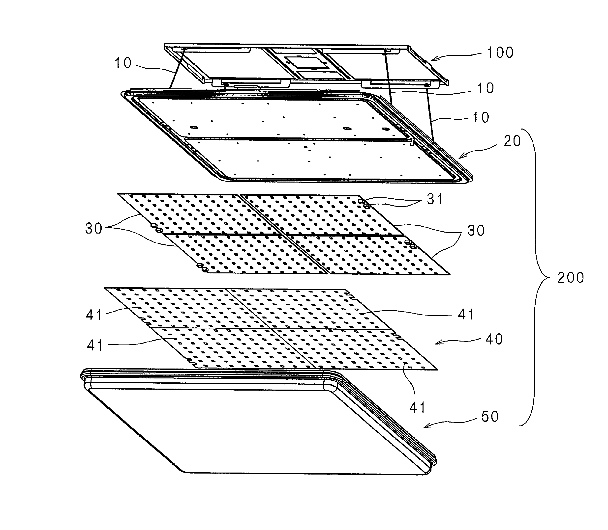
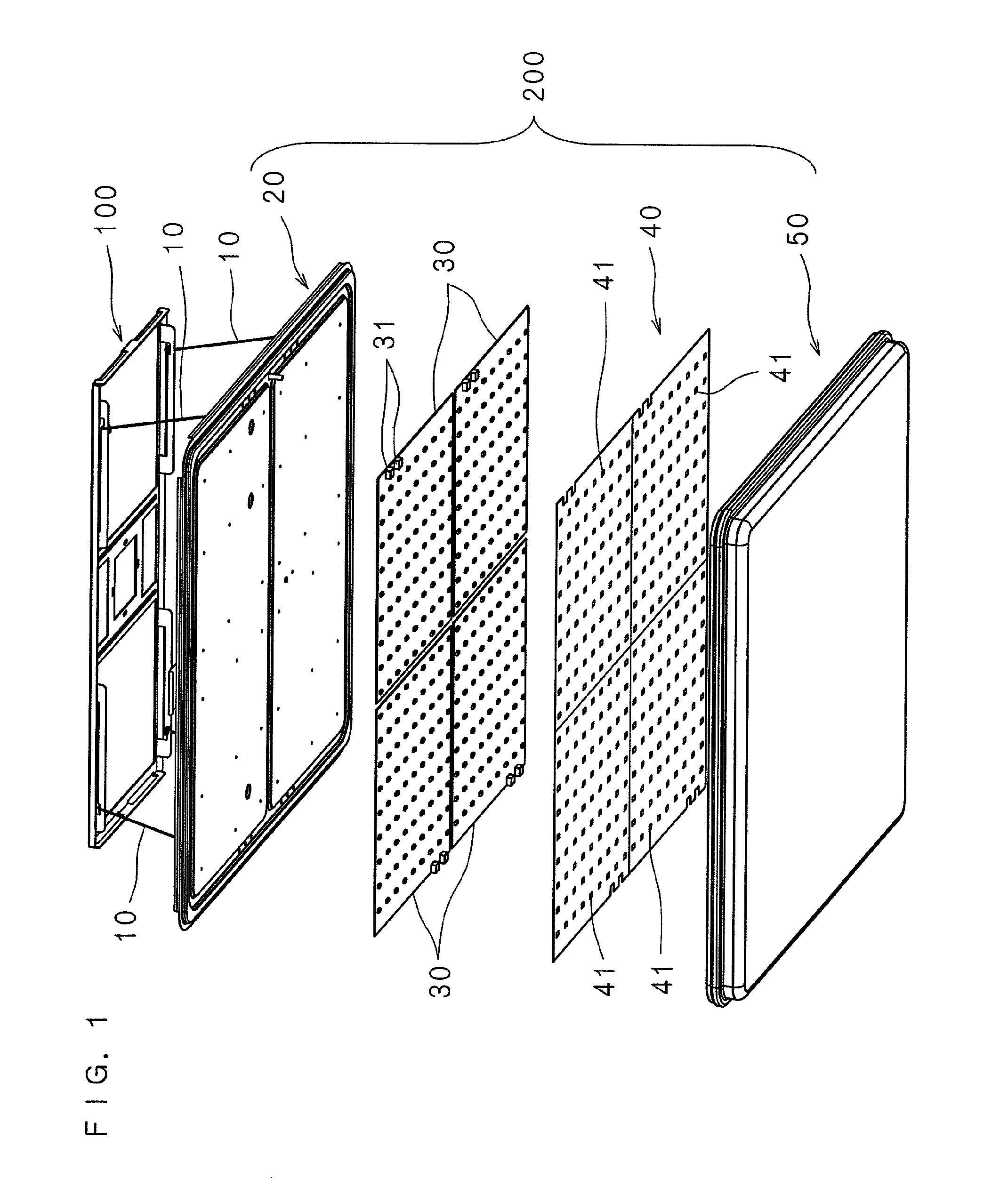
[0038]The present invention will be described below with reference to the drawings showing embodiments of the invention. FIG. 1 is a schematic exploded perspective view of a lighting apparatus according to an embodiment of the present invention. The lighting apparatus according to the invention includes a metal mounting 100 fixedly mounted at a needed place on a mounting surface, such as a ceiling or a wall, as a mounting member, holding metal fixtures 10 as a holding member, and a lighting apparatus body 200 that includes a chassis 20 to which the holding metal fixtures 10 are loosely fitted, a board 30 that is fixed to the chassis 20 and on which light emitting diodes are implemented as a luminous element, a reflecting panel 40, a cover (diffusing panel) 50 that covers a luminous surface constituted by the light emitting diodes, and so on. The lighting apparatus body 200 is held with the holding metal fixtures 10 in a manner that is separated from the metal mounting 100. In the re...

second embodiment

[0096]Although the front and back surfaces of the lighting apparatus according to the first embodiment are rectangular, shapes of the front and back surfaces of a lighting apparatus according to a second embodiment of the present invention are not limited to such a shape; that is, both the surfaces may be circular. In that case, the chassis 20 is shaped into a circle, and the length of each long side of the metal mounting 100 is made equal to the diameter of the circular chassis 20. The structure of the metal mounting 100 and the shape of the holding metal fixture 10 are the same as those described in the first embodiment.

[0097]FIG. 14 is a plan view of the board 30 according to the second embodiment. As shown in FIG. 14, the board 30 has a shape of a quarter of a circle; by adjacently placing the four boards 30, a circular luminous surface can be formed. And further, as in the case of the first embodiment, the plurality of diode sets, which each consist of the light emitting diode ...

third embodiment

[0098]FIG. 15 is a plan view of the board 30 according to a third embodiment. The third embodiment is different from the first embodiment in that the light emitting diodes 1 and 2 as luminous elements different in color temperature consisting the diode sets are staggerly arranged. That is, by viewing FIG. 15 in a state in which the connectors 31 are provided at the right-hand side of the board 30, it can be seen that the upper-left diode set is provided on the board 30 with the light emitting diode 1 sitting above the light emitting diode 2. With the diode set provided at the right of the upper-left diode set, the light emitting diode 2 sits above the light emitting diode 1. Likewise, the light emitting diodes 1 and 2 that constitute the diode sets adjacent to each other in the row and column directions are arrange staggerly.

[0099]By adjacently providing the light emitting diodes 1 and 2 that constitute one diode set, it is possible to prevent an occurrence of a problem that when ha...


PUM


Abstract

A lighting apparatus includes a metal mounting fixed to a needed place such as a ceiling or a wall, rod-shaped holding metal fixtures, and a lighting apparatus body constituted by a chassis to which one end portion of each holding metal fixture is loosely fitted, a board which is fixed to the chassis and on which light emitting diodes are mounted as luminous elements, a reflecting panel, a cover (diffusing panel) that covers the light emitting diodes, and so on. By inserting the lock section of the other end portion of each holding metal fixture into an insertion hole and then locking each holding metal fixture on the metal mounting, the lighting apparatus body is held in a state of being separated from the metal mounting.

Description

[0001]This application is the national phase under 35 U.S.C. §371 of PCT International Application No. PCT / JP2009 / 005825 which has an International filing date of Nov. 2, 2009 and designated the United States of America.BACKGROUND[0002]1. Technical Field[0003]The present invention relates to a lighting apparatus that includes a mounting member to be placed on a mounting surface such as a ceiling and that includes a lighting apparatus body with a light source to be mounted to the mounting surface through the mounting member.[0004]2. Description of Related Art[0005]In recent years, a new lighting apparatus, in which a light emitting diode or the like is used as a light source instead of a fluorescent lamp and an incandescent lamp, has been developed as a lighting apparatus in which a more power saving is achieved and which has a longer life. Such a lighting apparatus has a structure where a board on which a plurality of light emitting diodes (LEDs) are mounted is fitted to a bottom su...

Claims


Application Information

Patent Timeline
IPC IPC(8): F21S8/00F21S8/02F21S8/04H05B44/00
CPCF21S8/04F21V21/36H05B33/0857F21S8/033F21V23/026F21V23/06F21Y2101/02F21Y2105/001F21Y2113/005F21V23/0435F21Y2105/10F21Y2115/10F21Y2113/13H05B45/20F21V21/03
Inventor YASUOKA, NORIO
Owner SHARP KK
Why Eureka
Try Eureka