Polyaxial bushing for locking plate

a technology of locking bushings and polyaxial bushings, which is applied in the field of bone plates having locking bushings, can solve problems such as delay in surgical procedures

Active Publication Date: 2013-05-21
ARTHREX
View PDF27 Cites 60 Cited by
  • Summary
  • Abstract
  • Description
  • Claims
  • Application Information

AI Technical Summary

Benefits of technology

[0005]The present invention provides a bone plate, preferably a humeral plate, with a new design that prevents the bushing from rotating and / or dislodging from the screw hole during screw insertion. The bushing design of the present invention also allows the screw to be locked at variable angles.
[0006]The plate of the present invention is provided with through-holes having internal walls with at least one flat that is configured to align with a corresponding flat provided on the outer wall of the bushing. The bushing is inserted by orienting the bushing in a direction perpendicular to the through-hole of the plate (screw hole) so that the center of the bushing is aligned with the center of the through-hole and the flat on the bushing is aligned with the flat on the through-hole of the bone plate. The bushing is introduced into the through-hole until the centers are aligned, and then the bushing is rotated about 90 degrees so that the bushing is captured within the through-hole of the plate. Once captured, the bushing cannot rotate, dislodge from, or come out of the plate unless the bushing is turned 90 degrees. The flat on the bushing mates with the flat on the internal wall of the hole (screw hole) to prevent it from rotating within the screw hole. This important aspect avoids the need for a bushing guide during screw insertion.

Problems solved by technology

During insertion of the screws into the bone plate, the bushings may inadvertently rotate within the screw hole or even dislodge from the through-hole of the bone plate, causing a delay in the surgical procedure.

Method used


Image

  • Polyaxial bushing for locking plate
  • Polyaxial bushing for locking plate
  • Polyaxial bushing for locking plate

Examples


Embodiment Construction

[0027]The present invention provides a bone plate with a locking design that prevents the bushing from rotating and / or dislodging from the screw hole during screw insertion. The design of the plate and bushing of the present invention also allows the screw to lock at variable angles.

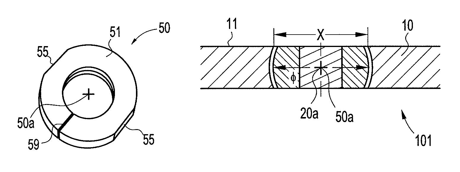
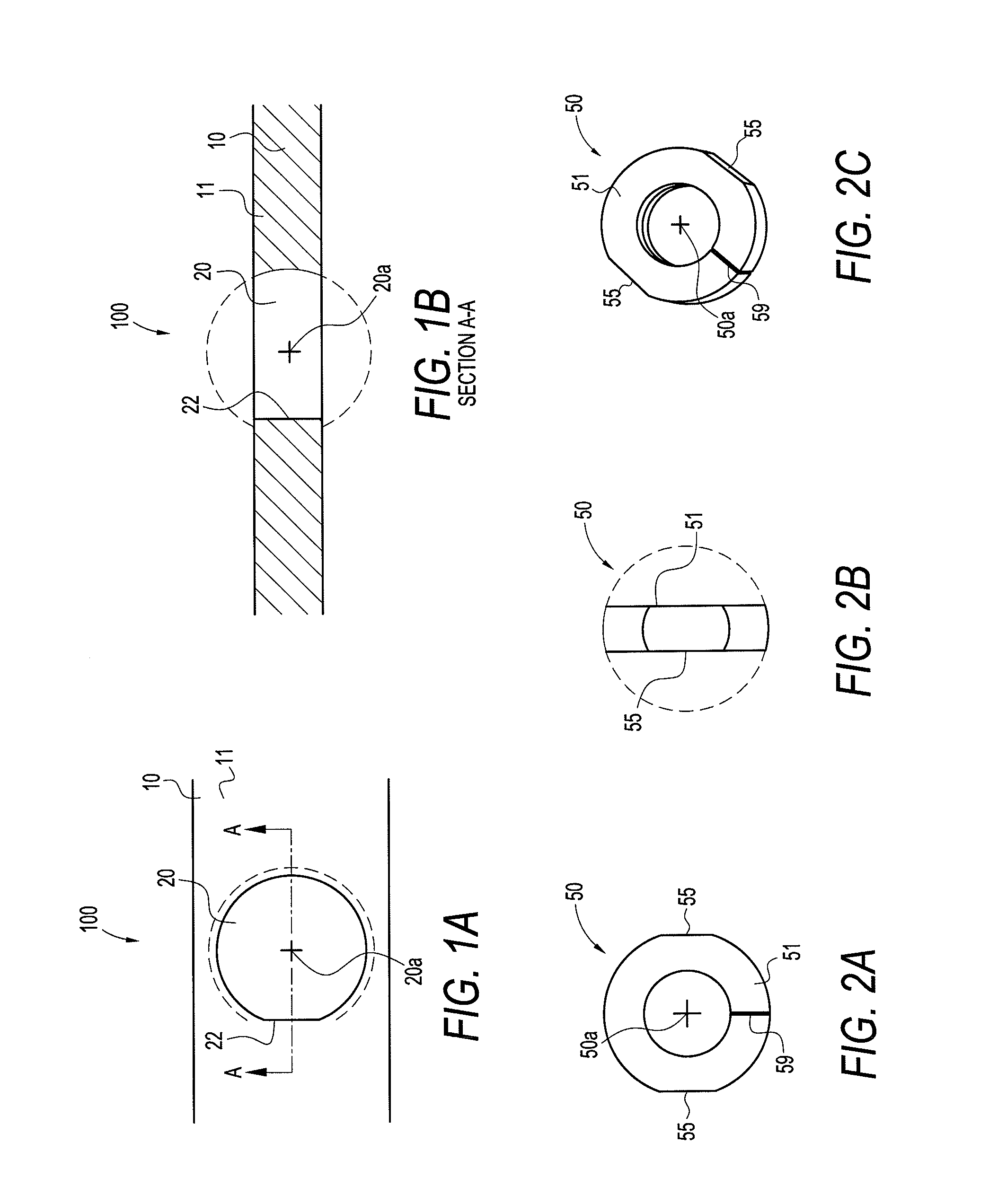
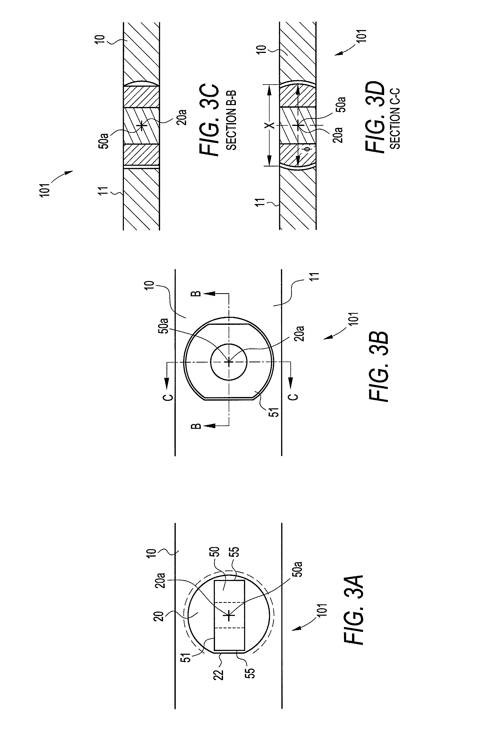
[0028]Referring now to the drawings, where like elements are designated by like reference numerals, FIGS. 1-6 illustrate a bone plate 100, 200 of the present invention provided with bushings 50, 150 that are designed to engage and lock within through-holes 20 of the plate, to form plate / bushing assembly 101, 201. As detailed below, the bushing 50, 150 is first inserted into the plate 100, 200 in a direction about perpendicular to the plate 100, 200, i.e., with the axis of the bushing oriented about perpendicularly to the axis of through-hole 20 of the plate, so that the center of the bushing is aligned with the center of the through-hole, and a flat on a lateral side of the bushing is aligned with a corr...


PUM


Abstract

A bone plate with a new design that prevents the bushing from rotating and / or dislodging from the screw hole during screw insertion. The plate is provided with through-holes having internal walls with at least one flat that is configured to align with a corresponding flat provided on the outer wall of the bushing. The bushing is inserted by orienting the bushing in a direction perpendicular to the through-hole of the plate so that the center of the bushing is aligned with the center of the through-hole and the flat on the bushing is aligned with the flat on the through-hole of the bone plate. The bushing is introduced into the through hole until the centers are aligned, and then the bushing is rotated about 90 degrees so that the bushing is captured within the through-hole of the plate. Once captured, the bushing cannot rotate, dislodge from, or come out of the plate unless the bushing is turned 90 degrees. The flat on the bushing mates with the flat on the internal wall of the hole (screw hole) to prevent it from rotating within the screw hole, and avoiding the need for a bushing guide during screw insertion.

Description

CROSS-REFERENCE TO RELATED APPLICATIONS[0001]This application claims the benefit of U.S. Provisional Application No. 61 / 259,500, filed Nov. 9, 2009, the entire disclosure of which is incorporated by reference herein.FIELD OF THE INVENTION[0002]The present invention relates to bone plates having locking bushings.BACKGROUND OF THE INVENTION[0003]Bone plates known in the art are typically provided with self-tapping bone plate screws that allow the bone plate to be secured to a surface of the bone. The screws are inserted through holes, which are formed into the bone plate and which contain washers or bushings that are rotatable in the holes. When the screw is inserted, the head of the screw typically spreads the bushing (for example, a split-sleeve bushing) as the screw advances and ultimately locks the bushing to the bone plate. The bushings may provide for variable angles of insertion for the screws. During insertion of the screws into the bone plate, the bushings may inadvertently r...

Claims


Application Information

Patent Timeline
Patent Type & Authority Patents(United States)
IPC IPC(8): A61B17/80
CPCA61B17/8047
Inventor DOONEY, JR., THOMASSODEIKA, JOHN A.
Owner ARTHREX
Why Eureka
Try Eureka