Cogeneration apparatus case venting system

a technology of cogeneration apparatus and venting system, which is applied in the direction of mechanical equipment, machines/engines, transportation and packaging, etc., can solve the problems of increasing noise accompanying ventilation, difficult efficient use of engine waste heat as heat source, and pressure loss in the air that flows through the ventilation-introducing channel, so as to achieve the effect of reducing noise and minimizing pressure loss

Active Publication Date: 2013-05-21
HONDA MOTOR CO LTD
View PDF5 Cites 4 Cited by
  • Summary
  • Abstract
  • Description
  • Claims
  • Application Information

AI Technical Summary

Benefits of technology

[0006]It is an object of the present invention to provide a cogeneration apparatus in which noise when driving fans (i.e., noise accompanying ventilation) can be reduced, and waste heat of a motor can be efficiently used a heat source.

Problems solved by technology

Accordingly, the noise when driving the fans (i.e., the noise accompanying ventilation) increases when the ventilation fan and the radiator fan are increased in size.
More heat than necessary is pulled from the engine and the heat exchanger, and making efficient use of the waste heat of the engine (motor) as a heat source is difficult.

Method used


Image

  • Cogeneration apparatus case venting system
  • Cogeneration apparatus case venting system
  • Cogeneration apparatus case venting system

Examples


Embodiment Construction

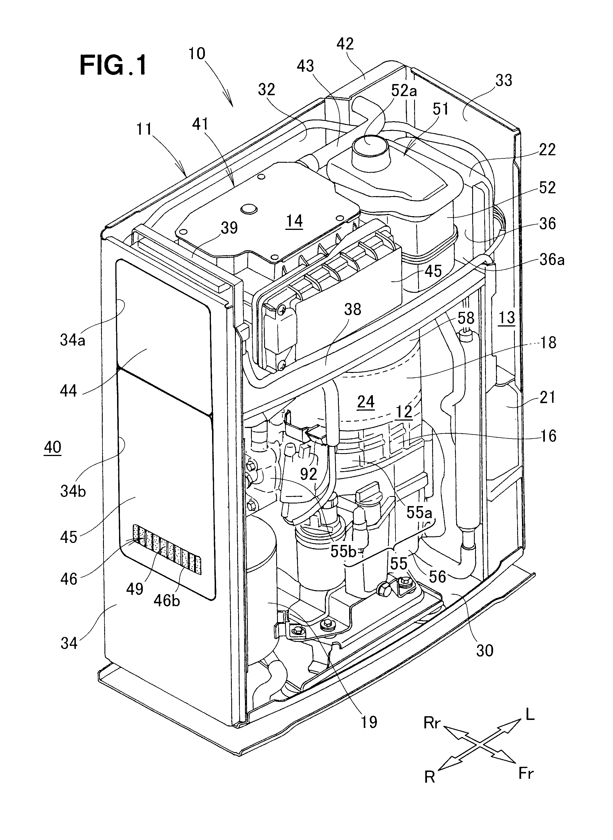
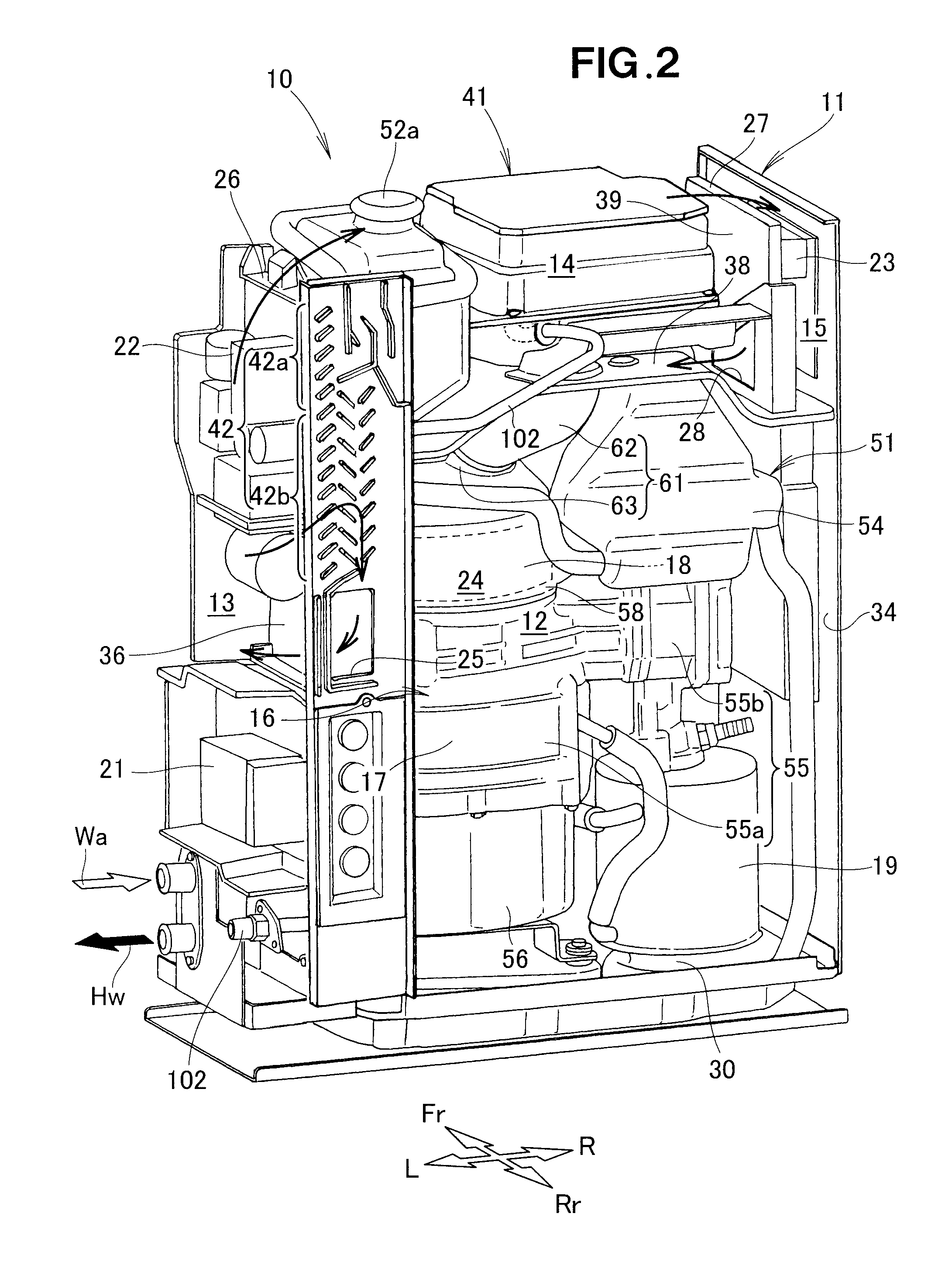
[0037]Throughout the description made as to the embodiment of the present invention with reference to the accompanying drawings, reference characters “Fr,”“Rr,”“L,” and “R” are used to represent “front,”“rear,”“left,” and “right”, respectively.

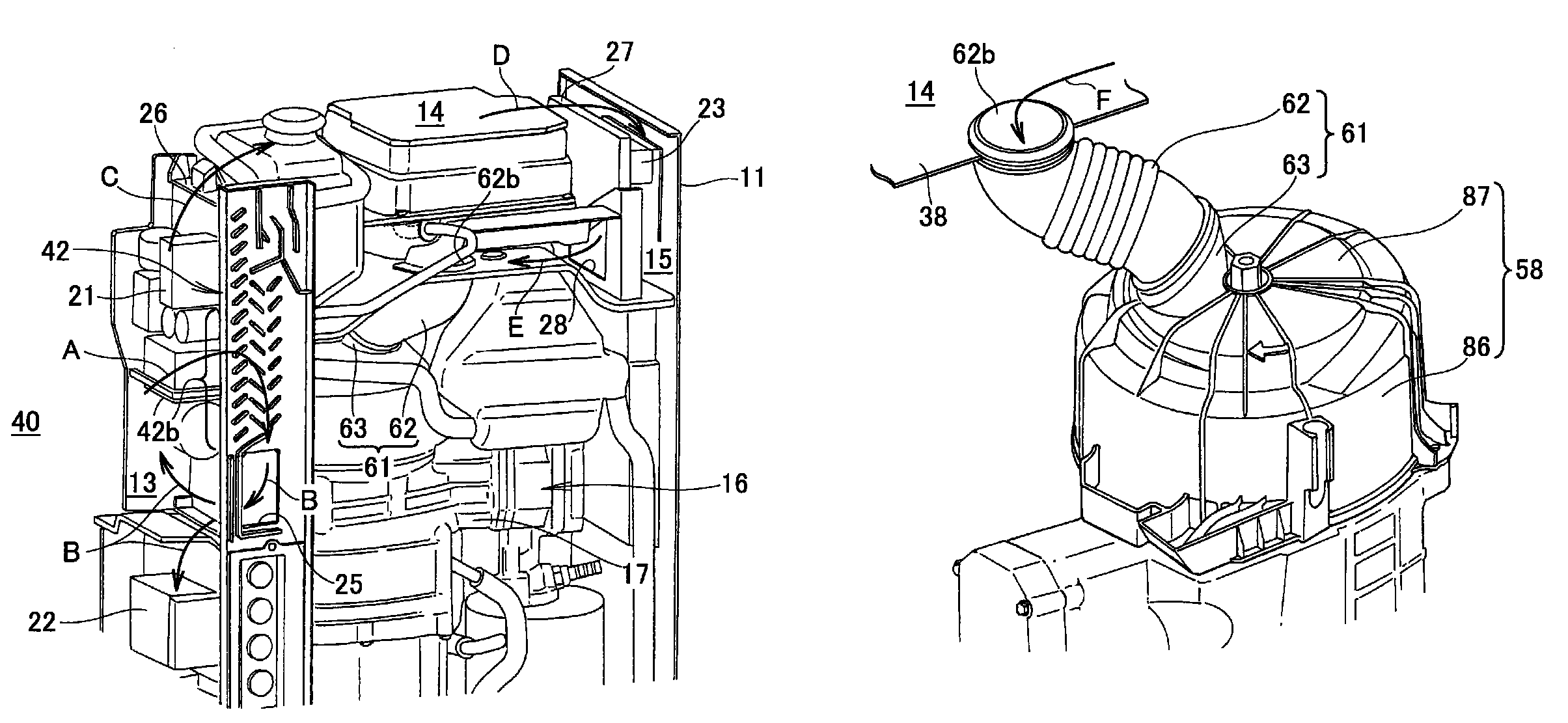
[0038]As shown in FIGS. 1 and 2, a cogeneration apparatus 10 is a combined heat-and-power apparatus that is provided with a cogeneration case (housing) 11, an engine (motor) 16 that is accommodated within the cogeneration case 11, an electrical generator 18, a heat exchanger 19, a first control part 21, a second control part 23, and a power converter part 22.

[0039]The cogeneration case 11 is formed into a substantially rectangular shape by a bottom part 30, a front panel (not shown), a rear panel 32, a left side panel 33, a right side panel 34, and a roof panel (not shown), whereby an interior space 24 is formed. An upper-panel aperture part 34a and a lower-panel aperture part 34b are formed in the right side panel 34. The right side panel 34 ...


PUM


Abstract

A cogeneration apparatus having a ventilation-introducing channel communicating an electrical-equipment compartment with a ventilation fan is disclosed. Driving the ventilation fan causes air to be led from an exterior of a cogeneration case through the electrical-equipment compartment to the interior of the ventilation-introducing channel. The air led to the interior of the ventilation-introducing channel is led to an electrical generator. The air led to the electrical generator is exhausted through a power-generation compartment to the exterior of the cogeneration case.

Description

FIELD OF THE INVENTION[0001]The present invention relates to a cogeneration apparatus capable of driving a ventilation fan to thereby ventilate the interior of a housing, and cooling electrical components, an electrical generator, and a motor.BACKGROUND OF THE INVENTION[0002]A well-known example of a cogeneration apparatus is disclosed in Japanese Patent Application Laid-Open Publication No. 2006-9678 (JP 2006-9678 A), in which an engine compartment is partitioned off within a housing (referred to as a “cogeneration case” below); an engine, an electrical generator, and a heat exchanger are provided to the engine compartment; and a ventilation fan and a radiator fan are provided for ventilating the engine compartment. Specifically, the interior of the cogeneration case is partitioned into the engine compartment, a duct compartment, a radiator compartment, and the like; and the engine, the electrical generator, and the heat exchanger are provided to the engine compartment. The ventila...

Claims


Application Information

Patent Timeline
Patent Type & Authority Patents(United States)
IPC IPC(8): B60L1/02
CPCF02B63/04H02K5/20H02K7/1815H02K11/046H02K9/06Y02E20/14Y02T10/16Y02T10/12H02K5/207H02K11/05
Inventor TAKITA, YOSHIHARUNAOI, ATSUMU
Owner HONDA MOTOR CO LTD
Why Eureka
Try Eureka