Fluid Heat Exchange Assembly, and Heat Management System of Vehicle

a technology of heat exchange and assembly, which is applied in the direction of indirect heat exchangers, conduit assemblies, lighting and heating apparatus, etc., can solve the problems of large installation space occupied by components and many pipes, and achieve the effect of reducing pipe arrangement, compact structure and small integral structur

Active Publication Date: 2020-01-30
ZHEJIANG SANHUA INTELLIGENT CONTROLS CO LTD
View PDF0 Cites 2 Cited by
  • Summary
  • Abstract
  • Description
  • Claims
  • Application Information

AI Technical Summary

Benefits of technology

[0014]An object of the present application is to provide a fluid heat exchange assembly and a thermal management system for vehicle, so that pipe arrangement is reduced, and the integral structure is small and compact.
[0023]The above technical solutions according to the present application include the fluid control module and the fluid heat exchange module. The fluid heat exchange assembly integrates functions of fluid communication and fluid heat exchange, reduces the pipe arrangement and has a compact structure and a small installation space, and the heat wasting on the pipelines is reduced.

Problems solved by technology

These components occupy a large installation space, and many pipes are required.

Method used


Image

  • Fluid Heat Exchange Assembly, and Heat Management System of Vehicle
  • Fluid Heat Exchange Assembly, and Heat Management System of Vehicle
  • Fluid Heat Exchange Assembly, and Heat Management System of Vehicle

Examples


first embodiment

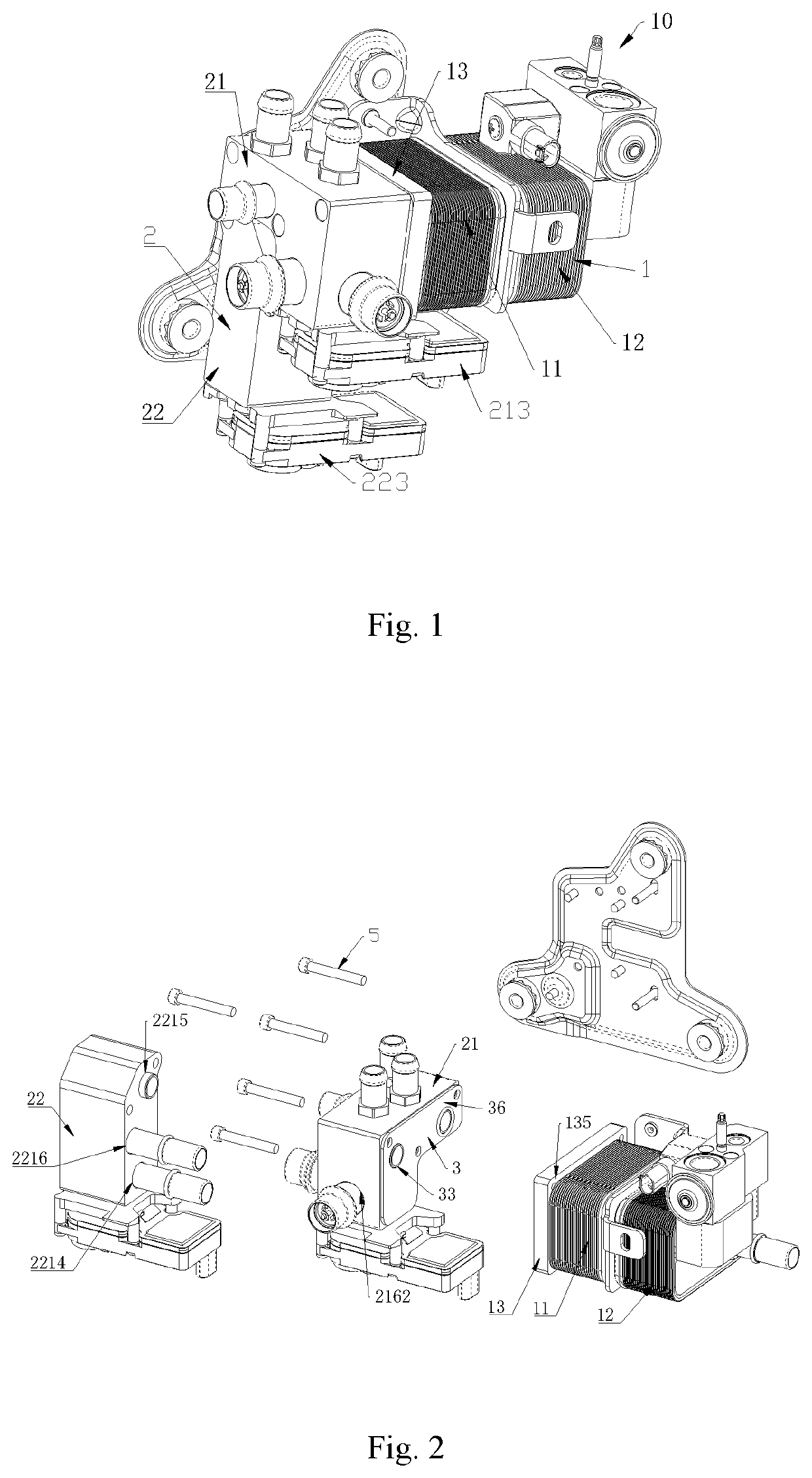
[0090]Reference is made to FIGS. 1 to 4, and FIG. 1 is a schematic view showing a fluid heat exchange assembly 10. The fluid heat exchange assembly 10 includes a fluid control module 2 and a fluid heat exchange module 1. Reference is made to FIGS. 32 to 35, FIG. 32 is a schematic view showing a fluid heat exchange assembly 20; FIG. 33 is an exploded schematic view showing the fluid heat exchange assembly 20; FIG. 34 is an exploded schematic view showing the fluid heat exchange assembly 30; FIG. 35 is an exploded schematic view showing the fluid heat exchange module 1′. The fluid heat exchange module 1 / 1′ includes at least one heat exchange core 11 and at least one connecting component 13, the heat exchange core 11 and the connecting component 13 are fixedly assembled through a fixing manner such as welding.

[0091]The fluid control module 2 includes a first connecting lateral portion 218, the fluid heat exchange module includes a second connecting lateral portion 136, the first connec...

second embodiment

[0177]As another embodiment, reference is made to FIGS. 38 and 39, FIG. 38 is a perspective exploded schematic view of a fluid heat exchange assembly 70; and FIG. 39 is an exploded schematic view of a fluid heat exchange module 1″. The fluid heat exchange assembly 70 includes a fluid control module 2 and a fluid heat exchange module 1″, where the fluid control module 2 refers to the fluid control module 2 in the above description, the fluid heat exchange module 1″ includes a first heat exchange core 11 and a second heat exchange core 12, the first heat exchange core 11 is fixedly assembled to the fluid control module 22, and the first heat exchange core 11 is fixedly assembled to the second heat exchange core 12. The fluid heat exchange assembly 60 further includes a seventh outer port 107 and an eighth outer port 108.

[0178]The fluid heat exchange module 1″ includes a first fluid communication cavity 14, a second fluid communication cavity 15 and a third fluid communication cavity 1...

third embodiment

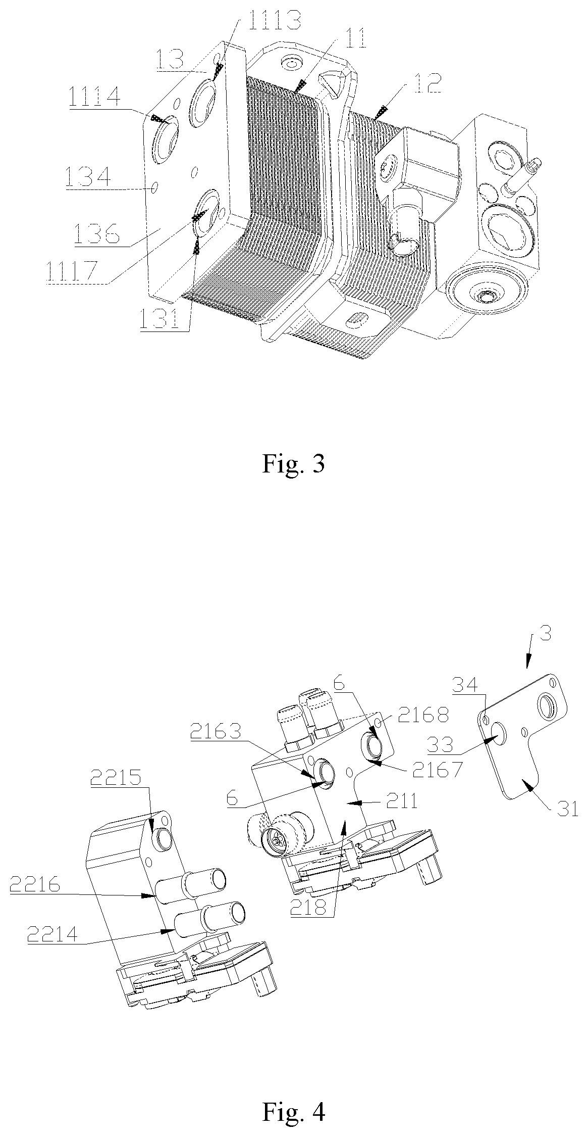
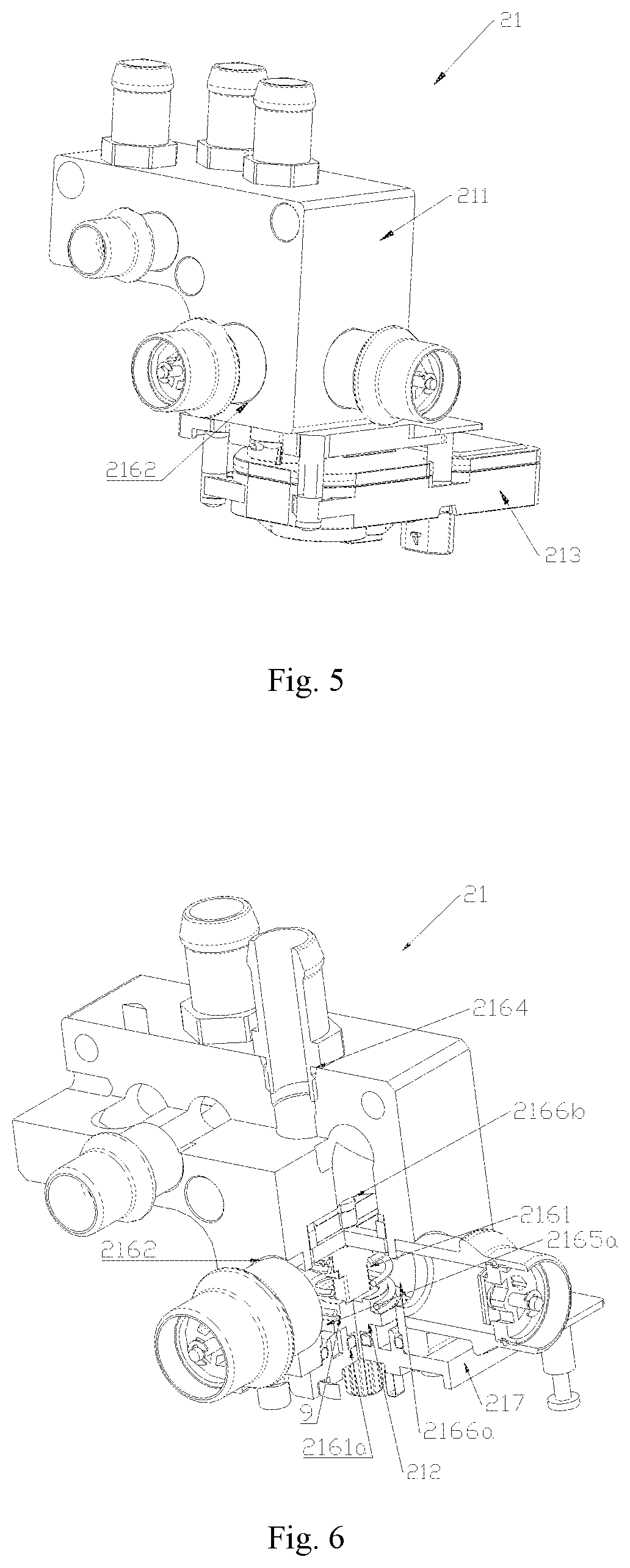
[0182]As another embodiment, reference is made to FIGS. 1 to 4 again, the fluid control module 2 includes a first fluid control device 21 and a second fluid control device 22, the first fluid control device 21 and the second fluid control device 22 are separately arranged, the first fluid control device 21 is fixedly assembled to the fluid heat exchange module 1, and the second fluid control device 22 is fixedly assembled to the fluid heat exchange module 1 through a fixing manner such as screwed connection. Referring to FIG. 2, the first fluid control device 21 includes a fourth mounting lateral portion 218, and the fourth mounting lateral portion 218 is fixedly assembled to the connecting lateral portion 136 of the connecting component 13. The second fluid control device 22 includes a fourth mounting lateral portion 218, and the fourth mounting lateral portion 218 is fixedly assembled to the connecting lateral portion 136 of the connecting component 13.

[0183]The connecting compone...


PUM


Abstract

A fluid heat exchange assembly includes a fluid control module and a fluid heat exchange module, the fluid control module includes a first connecting lateral portion, the fluid heat exchange module includes a second connecting lateral portion; the first connecting lateral portion and the second connecting lateral portion are oppositely and sealingly arranged; the fluid heat exchange module includes a heat exchange core and a connecting component fixed by welding; the fluid control module includes at least a first flow passage and a second flow passage; the fluid heat exchange module includes a first fluid communication cavity, and the second flow passage is in communication with the first fluid communication cavity; the connecting component includes a connecting channel, the connecting channel penetrates through the connecting component. The fluid heat exchange assembly reduces pipeline arrangement and is of a small and compact integral structure.

Description

CROSS-REFERENCE TO RELATED APPLICATIONS[0001]The present application claims priority to the following ten Chinese Patent Applications, the entire disclosures of which are incorporated herein by reference:[0002]1. Chinese Patent Application No. 201610986593.2 titled “FLUID HEAT EXCHANGE ASSEMBLY AND THERMAL MANAGEMENT SYSTEM FOR VEHICLE”, filed with the Chinese State Intellectual Property Office on Nov. 9, 2016;[0003]2. Chinese Patent Application No. 201610986726.6 titled “FLUID HEAT EXCHANGE ASSEMBLY AND THERMAL MANAGEMENT SYSTEM FOR VEHICLE”, filed with the Chinese State Intellectual Property Office on Nov. 9, 2016;[0004]3. Chinese Patent Application No. 201610986790.4 titled “FLUID HEAT EXCHANGE ASSEMBLY”, filed with the Chinese State Intellectual Property Office on Nov. 9, 2016;[0005]4. Chinese Patent Application No. 201611126787.1 titled “FLUID HEAT EXCHANGE ASSEMBLY”, filed with the Chinese State Intellectual Property Office on Dec. 9, 2016;[0006]5. Chinese Patent Application N...

Claims


Application Information

Patent Timeline
Patent Type & Authority Applications(United States)
IPC IPC(8): B60H1/00
CPCB60H1/00278B60H1/00342B60H1/00885F28F27/02F16K11/074F28D9/005F28F9/0253F28F2250/06F28F2275/06B60H1/3229B60H1/00485F28F9/0246F28F9/04F28D9/0031F16K11/072F28F2230/00F28D2021/008
Inventor CHEN, ZHENWENZHANG, JIANMINQIAN, KEZHEHU, SHIFENG
Owner ZHEJIANG SANHUA INTELLIGENT CONTROLS CO LTD
Why Eureka
Try Eureka