Bowl flushing control device of low tank type toilet

a control device and toilet technology, applied in the field of low-tank toilets, can solve the problems of poor flushing effect, high cost, and inconvenience for package and transportation, and achieve the effects of stable discharge volume, good flushing effect, and free of place and working pressur

Inactive Publication Date: 2019-05-07
XIAMEN R&J PRECISION TECH CO LTD
View PDF9 Cites 0 Cited by
  • Summary
  • Abstract
  • Description
  • Claims
  • Application Information

AI Technical Summary

Benefits of technology

[0008]Compared to the existing known technology, the present invention has following effects:
[0009]1. The present invention can not only guide the flushing water from the inlet valve to the flushing ring passage of the toilet the flush the bowl of the toilet during discharging, but also bring the effects: the first floater is directly disposed in the toilet tank, to directly sense the height of the water level in the tank, and the present invention uses the first floater to restrict on the control rod to make the switch point of close of the waterway switch component completely controlled by the first floater and none business with the inlet pressure of the inlet valve and other components. Therefore, the varied of the inlet pressure influences little, with the same inlet valve and discharge valve, based on a good flushing effect, the present invention has advantages of stable discharge volume, free of place and working pressure and wide applicability.
[0010]2. The present invention has advantages of small and compact structure, less components and low sealing need, thus decreasing the manufacturing difficulty of the product and greatly increasing the yield of the products.
[0011]3. The present invention is further disposed with two water replenishing passages and a water replenishing adjust piece, making the water replenishing volume adjustable for different toilets, protruding a good applicability for various toilets.
[0012]4. The waterway switch component of the present invention is preferred a water stop plate with its axis parallel to or vertical to its rotating axis that brings advantages that the water stop plate needs to rotate in a large angle to completely open or close the waterway of the water supply pipe, therefore the space is small that benefits a smaller size and compacter structure of the entire structure.

Problems solved by technology

But this kind of toilet occupies large space, and it is not convenient for package and transportation and it costs high.
However, this low tank type toilet has disadvantages: the height difference between the water level in the tank and the lip portion of the toilet (the flushing ring portion) is small, even the water level in the tank is lower than the lip portion, resulting in that when water flushes, the tank can provide enough water to satisfy the bowl flushing need.
However, this low tank toilet still has disadvantages: the pipe body (220) is connected to the inlet valve and the tank, so water level of the clean water flushing pipe (110) and the water level of the tank directly influence the water level in the pipe (220), the inlet water from the inlet valve provides pump force to the water in the pipe (220), water in the pipe (220) is directly pumped to the toilet.
Therefore, the inlet pressure of the inlet valve and the pump performance directly influence the water level in the pipe, and influencing the switch of the water supply switch component.
During flushing the ring passage, it may lead to bad flushing effect when the water supply volume is not enough or waste water when the water supply volume is abundant.
In addition, this solution has disadvantages of many components and complicated structure.

Method used


Image

  • Bowl flushing control device of low tank type toilet
  • Bowl flushing control device of low tank type toilet
  • Bowl flushing control device of low tank type toilet

Examples


first embodiment

The First Embodiment

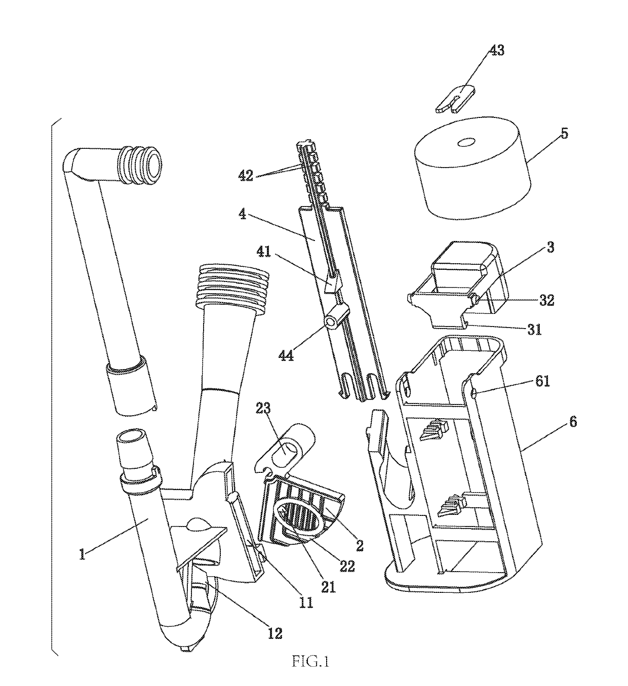
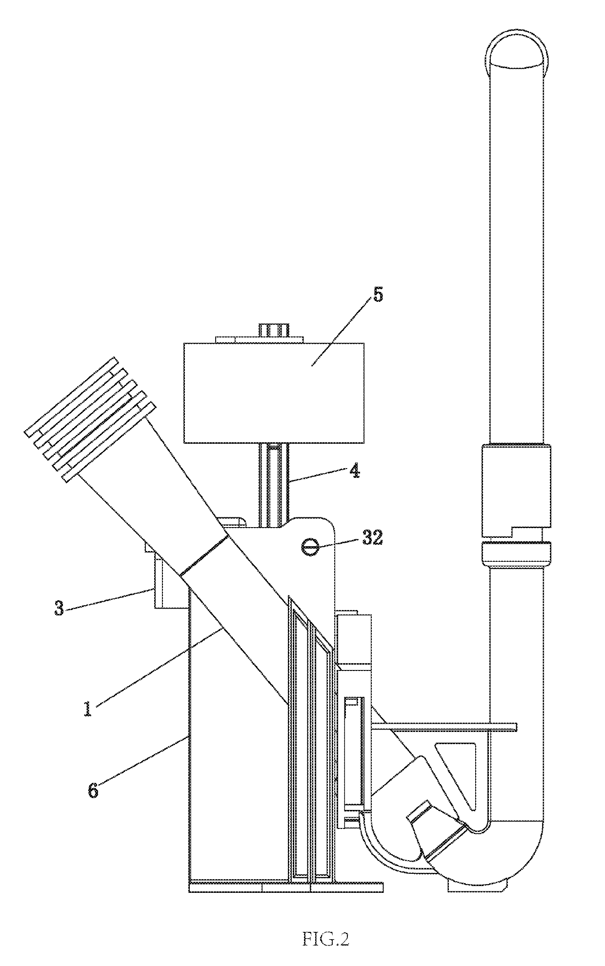
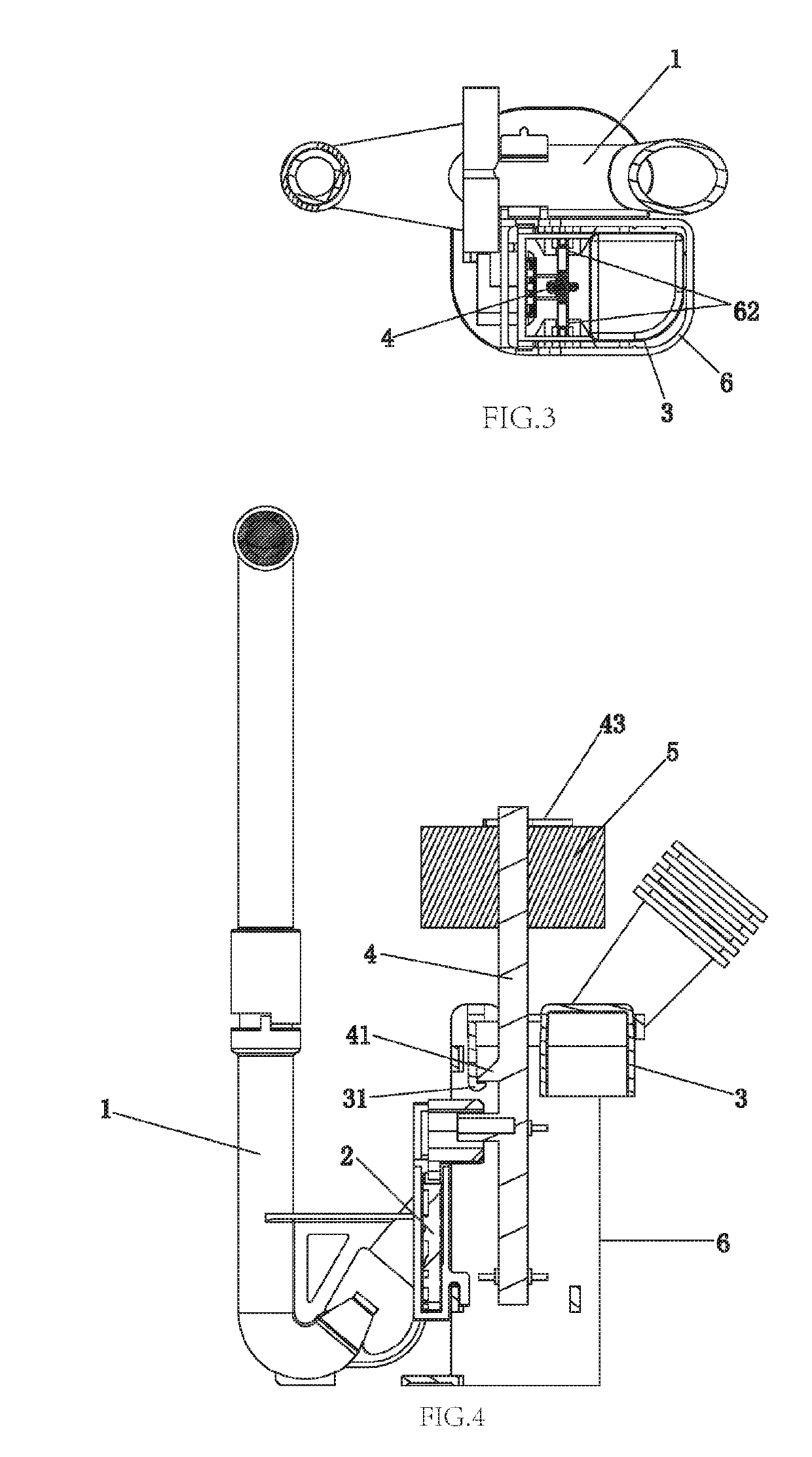
[0048]Referring to FIGS. 1-7, a bowl flushing control device of low tank type toilet comprises:

[0049]a water supply pipe 1 used to supply flushing water from an inlet valve to the flushing ring passage or the connecting pipes, the water supply pipe 1 is disposed with a working chamber 11, the working chamber 11 is connected to the waterways at two sides of the water supply pipe 1 and the toilet tank; herein, the two waterways at two sides of the water supply pipe mean that the interior of the water supply pipe 1 is divided to two portions of waterways by the working chamber, the two portions of waterways are connected by the working chamber; the side surface of the water supply pipe 1 is further disposed with a connecting hole 12, which is disposed at the front side of the working chamber 11 and connects the toilet tank and working chamber 11;

[0050]a waterway switch component rotatably assembled to the working chamber 11 to open and close the waterway of the wate...

second embodiment

The Second Embodiment

[0069]Referring to FIGS. 8-12, this embodiment differs from the first embodiment in that: The first floater (the float bowl 3) is longitudinally movably assembled to the rack 6, and it moves downwardly when the water level in the toilet tank is lower than the working level; a transmission mechanism 7 is further provided, the float bowl 3 is linked to the control rod 4 by the transmission mechanism 7.

[0070]In this embodiment, the transmission mechanism 7 comprises a slide block 71 horizontally slidably assembled to the rack 6, a driving component 73 rotatably assembled to the rack 6 and an elastic element; the side surface of the control rod 4 is disposed with a protruding portion similar to the first embodiment, the slide block 71 is disposed with a hanging portion 74 to hang to the protruding portion 41, the external side surface of the hanging portion 74 is disposed with a guide incline surface faced downwardly; one end of the driving component 73 is movably c...

third embodiment

The Third Embodiment

[0076]Referring to FIGS. 13-15, this embodiment differs from the first embodiment in that: The activation component is a pull rod 8 linked to the discharging operation mechanism of the toilet, the pull rod 8 is synchronously coupled to the control rod 4. In detail, the pull rod 8 is rotatably connected to the top portion of the rack 6, the pull rod 8 is disposed with a second connecting portion at the radial direction of the rotating shaft; the second connecting portion is disposed with a second elongate hole 81, the side surface of the top portion of the control rod 4 is disposed with a pin shaft 45, the pin shaft 45 is slidably inserted to the second elongate hole 81.

[0077]When the water level in the tank is lower than the working level of the float bowl 3, the float bowl 3 rotates in the clockwise direction to make the hook 31 separate from the protruding portion 41 of the control rod 4, the control rod 4 moves downwardly by the gravity and drives the water st...


PUM


Abstract

A bowl flushing control device of low tank type toilet has a water supply pipe with a working chamber; a waterway switch component used to open and close the waterway of the water supply pipe; a first floater being floatable in the toilet tank, the first floater takes action when the water level in the water tank is lower than the working level; a control rod being movable up and down, the first floater is movably coupled to the control rod; the control rod is movably connected to the waterway switch component to move downwardly and drive the waterway switch component to close the waterway of the water supply pipe when the first floater takes off restriction on the control rod; a activation component used to control the control rod to move upwardly to reset and coupled to the control rod.

Description

FIELD OF THE INVENTION[0001]The present invention relates to a low tank toilet, particularly to a bowl flushing control device of low tank type toilet.BACKGROUND OF THE INVENTION[0002]Traditional toilet disposes the tank on the seat body. Due to the water gravity, water in the tank easily enters the flushing ring passage of the toilet to flush the bowl. But this kind of toilet occupies large space, and it is not convenient for package and transportation and it costs high. Therefore, there is a kind of toilet with low tank; the tank is disposed at the interior portion of the rear side of the seat body that it reduces much occupying space. However, this low tank type toilet has disadvantages: the height difference between the water level in the tank and the lip portion of the toilet (the flushing ring portion) is small, even the water level in the tank is lower than the lip portion, resulting in that when water flushes, the tank can provide enough water to satisfy the bowl flushing ne...

Claims


Application Information

Patent Timeline
Patent Type & Authority Patents(United States)
IPC IPC(8): E03D1/24E03D1/32
CPCE03D1/32E03D1/24
Inventor TANG, YAPING
Owner XIAMEN R&J PRECISION TECH CO LTD
Why Eureka
Try Eureka