Exhaust gas assembly for a patient interface device

Active Publication Date: 2013-08-22
KONINKLIJKE PHILIPS ELECTRONICS NV
View PDF3 Cites 12 Cited by
  • Summary
  • Abstract
  • Description
  • Claims
  • Application Information

AI Technical Summary

Benefits of technology

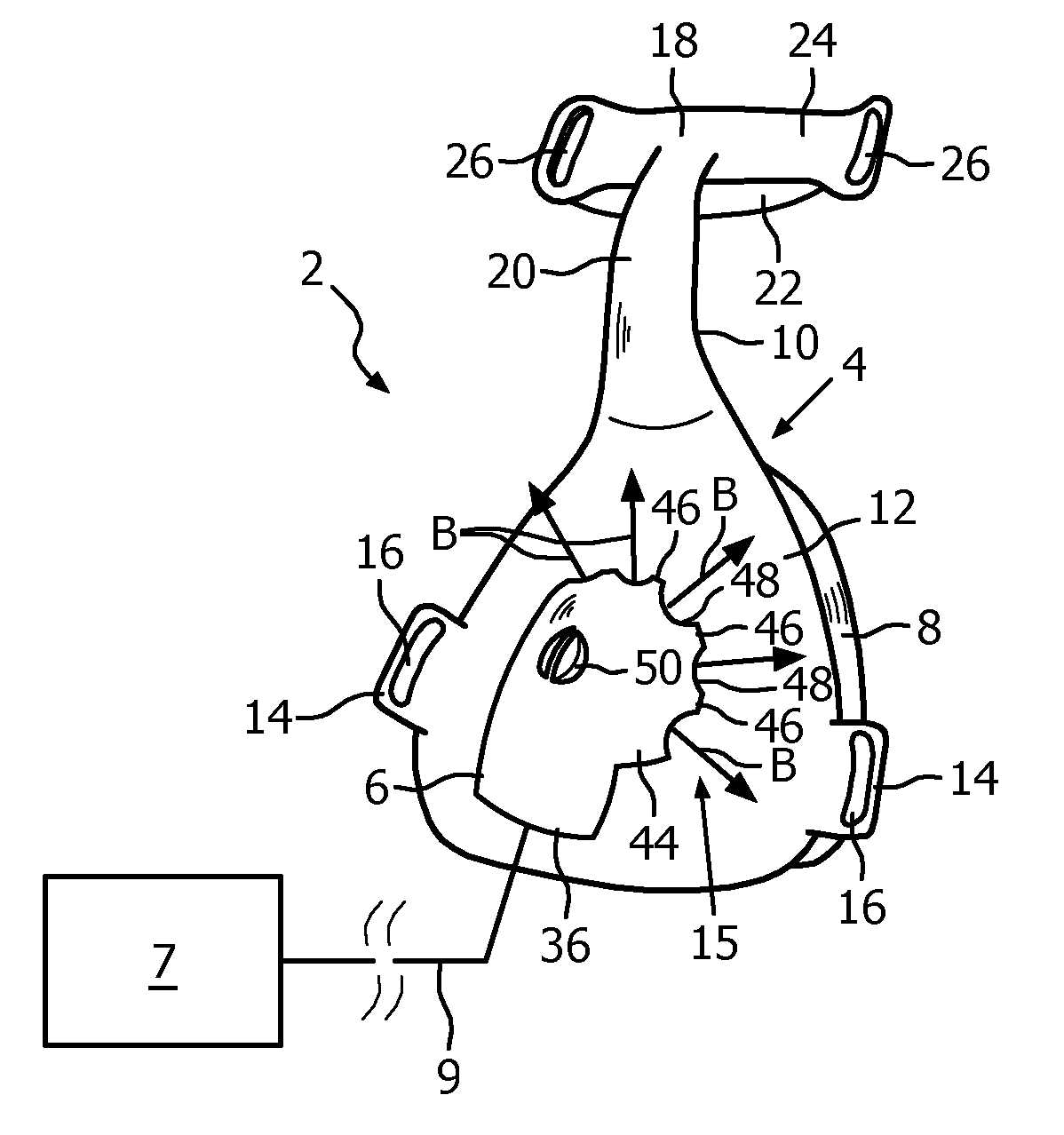
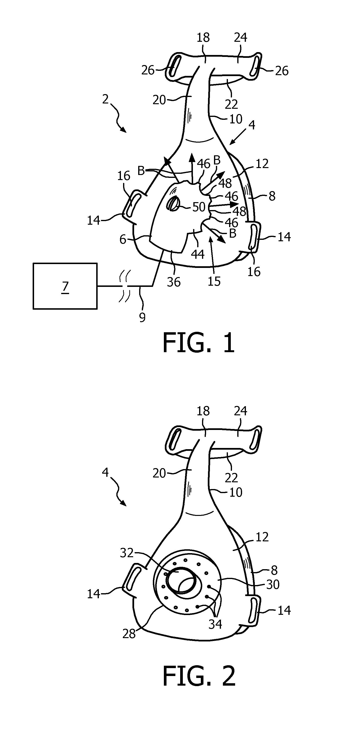
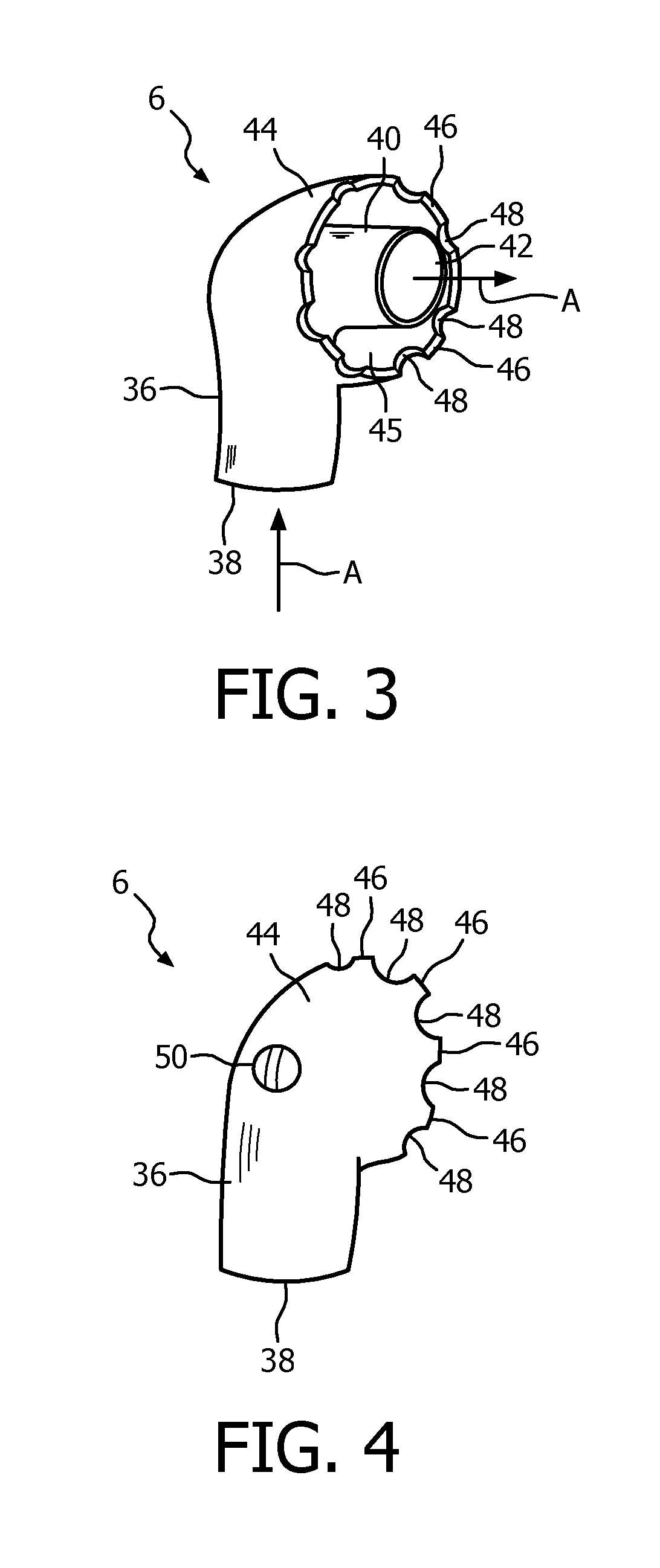
[0010]Accordingly, it is an object of the present invention to provide a patient interface device with an exhaust gas assembly that overcomes the shortcomings of conventional patient interface devices. This object is achieved according to one embodiment of the present invention by providing a patient interface device that includes a cushion and a frame having a faceplate portion in which the cushion is coupled to the frame. The faceplate portion has a main orifice and one or more holes adjacent the main orifice. The main orifice and the one or more holes extend through the frame. The patient interface device further includes a fluid coupling conduit having an inlet end, an outlet end fluidly coupled to the inlet end, and a hood member having one or more openings provided on an outer periphery thereof. The inlet end is structured to receive a flow of breathing gas, and the outlet end is fluidly coupled to the main orifice to deliver the flow of breathing gas to the main orifice. The hood member surrounds the outlet end, is disposed over the one or more holes, and engages the faceplate portion in a manner wherein exhalation gasses will flow through the one or more holes and be captured by the hood member and directed through the one or more openings.
[0011]In another embodiment, a method of controlling gas flow through a patient interface device is provided that includes delivering a positive pressure flow of breathing gas to a patient through a coupling conduit fluidly coupled to a main orifice provided in a faceplate portion of the patient interface device, directing exhaled gasses exhaled by the patient to pass through one or more holes provided in the faceplate portion adjacent the main orifice, capturing the exhaled gasses in a chamber formed over the one or more holes and the main orifice, and directing the exhaled gasses through one or more openings provide

Problems solved by technology

While numerous different configurations for such exhaust gas assemblies are known, conventional exhaust gas assemblies can suffer excessive noise as the flow of exhaust gas passes through the exhaust gas assembly.
This noise is undesirable in that it may disturb the sleep of the patient or the patient's bed partner.
Another prob

Method used


Image

  • Exhaust gas assembly for a patient interface device
  • Exhaust gas assembly for a patient interface device
  • Exhaust gas assembly for a patient interface device

Examples


Embodiment Construction

[0029]As used herein, the singular form of “a”, “an”, and “the” include plural references unless the context clearly dictates otherwise. As used herein, the statement that two or more parts or components are “coupled” shall mean that the parts are joined or operate together either directly or indirectly, i.e., through one or more intermediate parts or components, so long as a link occurs. As used herein, “directly coupled” means that two elements are directly in contact with each other. As used herein, “fixedly coupled” or “fixed” means that two components are coupled so as to move as one while maintaining a constant orientation relative to each other.

[0030]As used herein, the word “unitary” means a component is created as a single piece or unit. That is, a component that includes pieces that are created separately and then coupled together as a unit is not a “unitary” component or body. As employed herein, the statement that two or more parts or components “engage” one another shal...


PUM


Abstract

A patient interface device (2, 60, 160, 204) includes a cushion (8, 66, 210), a frame (10, 68, 162, 206) having a faceplate portion. The cushion is coupled to the frame. The faceplate portion has a main orifice and holes adjacent the main orifice. The device further includes a coupling conduit (6, 64, 164, 212) having an inlet end, an outlet end coupled to the inlet end, and a hood member having openings provided on an outer periphery thereof. The inlet end is structured to receive a flow of breathing gas. The outlet end is coupled to the main orifice to deliver the flow of breathing gas to the main conduit. The hood member surrounds the outlet end and is disposed over the holes such that exhalation gasses will through the holes and be captured by the hood member and directed through the openings.

Description

CROSS-REFERENCE TO RELATED APPLICATIONS[0001]This patent application claims the priority benefit under 35 U.S.C.§119(e) of U.S. Provisional Application No. 61 / 405,799 filed on Oct. 22, 2010, the contents of which are herein incorporated by reference.BACKGROUND OF THE INVENTION[0002]1. Field of the Invention[0003]The present invention relates to non-invasive ventilation and pressure support systems, and, in particular, to a patient interface device that may be used with such system to deliver gas to a patient that includes an exhaust gas assembly for reducing noise caused by patient exhalation and / or diffusing the patient exhalation flow.[0004]2. Description of the Related Art[0005]There are numerous situations where it is necessary or desirable to deliver a flow of breathing gas non-invasively to the airway of a patient, i.e., without intubating the patient or surgically inserting a tracheal tube in their esophagus. For example, it is known to ventilate a patient using a technique k...

Claims


Application Information

Patent Timeline
IPC IPC(8): A61M16/06A61M16/08A61M16/00
CPCA61M16/06A61M2205/42A61M16/0057A61M16/0633A61M16/0816A61M16/0875A61M16/0683A61M16/0605A61M16/0644
Inventor HAIBACH, RICHARD THOMAS
Owner KONINKLIJKE PHILIPS ELECTRONICS NV
Why Eureka
Try Eureka