Electronic tag for passive tire pressure detection and detection method

An electronic label and detection method technology, which is applied to record carriers, instruments, computer parts, etc. used in machines, can solve the problems of complex structure, increased manufacturing cost, relatively high requirements for design and micro-fabrication process, and achieves small and compact structure. Detecting effects with simple structures

Pending Publication Date: 2019-12-06
苏州晟达力芯电子科技有限公司
View PDF0 Cites 0 Cited by
  • Summary
  • Abstract
  • Description
  • Claims
  • Application Information

AI Technical Summary

Problems solved by technology

[0003] The above-mentioned solution involves many components, the structure is relatively complex, and the structure is small and compact, which requires relatively high requirements for design and micro-fabrication process, and the corresponding manufacturing cost will also increase

Method used


Image

  • Electronic tag for passive tire pressure detection and detection method
  • Electronic tag for passive tire pressure detection and detection method
  • Electronic tag for passive tire pressure detection and detection method

Examples


Embodiment 1

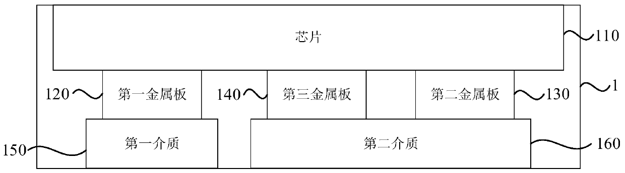
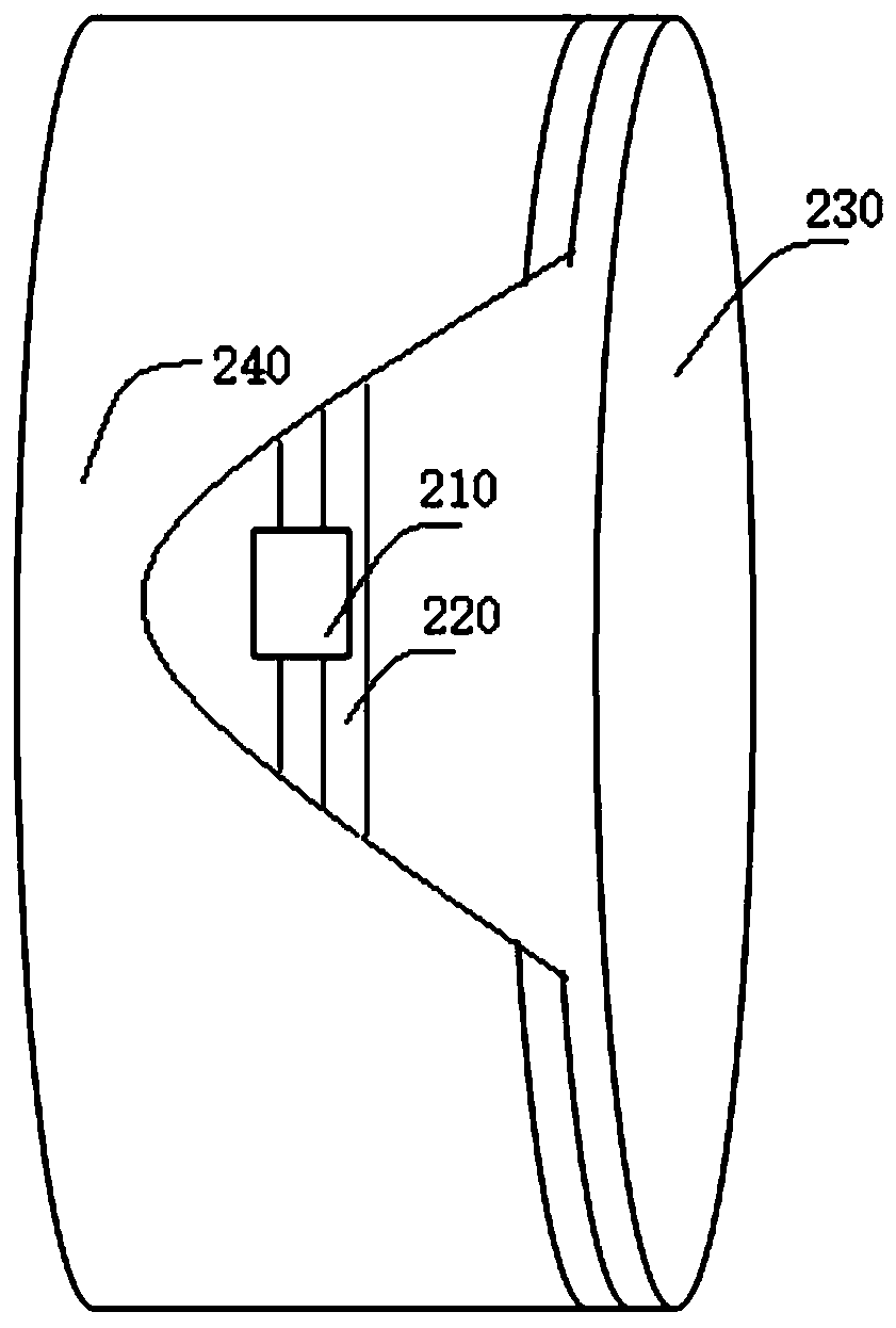
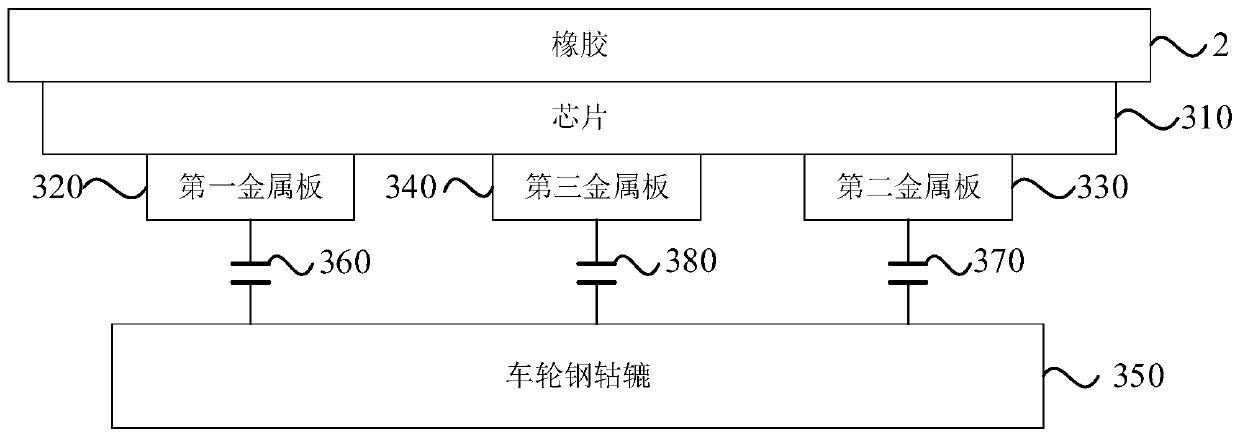
[0023] figure 1 The structural diagram of the electronic tag for passive tire pressure detection provided by Embodiment 1 of the present invention, figure 2 It is a schematic diagram of the electronic label for passive tire pressure detection in Embodiment 1 of the present invention attached to the steel wheel of the tire wheel, image 3 It is a schematic diagram of capacitance formed by each metal plate of the electronic tag for passive tire pressure detection in Embodiment 1 of the present invention. refer to figure 1 , the electronic tag includes a chip 110, a first metal plate 120, a second metal plate 130, a third metal plate 140, a first medium 150 and a second medium 160;

[0024] Wherein, the first metal plate 120 is electrically connected to the first solder joint of the chip 110, the second metal plate 130 is electrically connected to the second solder joint of the chip 110, and the third metal plate 140 is electrically connected to the third solder joint of the c...

Embodiment 2

[0033] On the basis of the above embodiments, this embodiment describes the structure of the antenna part of the electronic tag. Figure 4 It is a structural diagram of an electronic tag for passive tire pressure detection according to Embodiment 2 of the present invention, Figure 5 It is a schematic diagram of an electronic tag for passive tire pressure detection in Embodiment 2 of the present invention, refer to Figure 4 , the electronic tag also includes an antenna 420, the first soldering point 411 is the first antenna connecting soldering point 421, the second soldering point 412 is the second antenna connecting soldering point 422, the first soldering point 421 of the antenna 420 is connected to the first soldering point 411 is electrically connected, and the second soldering point 422 of the antenna 420 is electrically connected to the second soldering point 412 .

[0034] Wherein, the first antenna connection pad 421 is shared with the first pad 411 for connecting t...

Embodiment 3

[0038] Image 6The flow chart of the passive tire pressure detection method provided by Embodiment 3 of the present invention, this embodiment is applicable to the realization of the tire pressure detection process, and the method can be implemented by the electronic tag for passive tire pressure detection described in any embodiment of the present invention To execute, specifically include the following steps:

[0039] Step 610, detecting the first capacitance formed by the first metal plate, the second capacitance formed by the second metal plate, and the third capacitance formed by the third metal plate;

[0040] Wherein, the chip can detect the first capacitance formed by the first metal plate, the second capacitance formed by the second metal plate, and the third capacitance formed by the third metal plate.

[0041] Step 620: Determine the change of the tire pressure according to the change of the first capacitor, the second capacitor and the third capacitor.

[0042] W...


PUM


Abstract

The embodiment of the invention discloses an electronic tag for passive tire pressure detection and a detection method. The electronic tag comprises a chip, a first metal plate, a second metal plate,a third metal plate, a first medium and a second medium. The first metal plate is electrically connected with a first welding spot of the chip, the second metal plate is electrically connected with asecond welding spot of the chip, and the third metal plate is electrically connected with a third welding spot of the chip. The first metal plate, the second metal plate and the third metal plate arepositioned on one side far away from the chip and are not overlapped with one another. The first medium is located on the side, away from the chip, of the first metal plate and overlaps with the firstmetal plate. The second medium is located on the sides, away from the chip, of the second metal plate and the third metal plate and overlaps with the second metal plate and the third metal plate, andthe effects of being simple in detection structure, capable of being completely implanted into a tire, free of maintenance and capable of detecting tire pressure changes without an external power source are achieved.

Description

technical field [0001] Embodiments of the present invention relate to tire pressure detection technology, in particular to an electronic label and detection method for passive tire pressure detection. Background technique [0002] Tire pressure detection is one of the important technologies to prevent tire blowout accidents and protect the stable and safe driving of vehicles. According to the configuration, tire pressure detection devices are mainly divided into two types: active type and passive type. Due to factors such as size, weight, power supply and installation inconvenience, passive tire pressure detection is becoming more and more popular. [0003] The above-mentioned solution involves many components, and the structure is relatively complicated, and the structure is small and compact, and the requirements for design and micro-fabrication process are relatively high, and the corresponding manufacturing cost will also increase. Contents of the invention [0004] ...

Claims


Application Information

Patent Timeline
Patent Type & Authority Applications(China)
IPC IPC(8): G06K19/077
CPCG06K19/07749
Inventor 万小凤
Owner 苏州晟达力芯电子科技有限公司
Why Eureka
Try Eureka