Slider for slide fastener

a slide and fastener technology, applied in the direction of slide fasteners, press-button fasteners, snap fasteners, etc., can solve the problems of complex manipulation, reduce the frictional force between the attachment/detachment, and reduce the amount of abrasion.

Active Publication Date: 2013-06-04
YKK CORP
View PDF13 Cites 9 Cited by
  • Summary
  • Abstract
  • Description
  • Claims
  • Application Information

AI Technical Summary

Benefits of technology

[0020]In the present invention, when each the cantilever engagement pieces is engaged with the attachment / detachment head, the cantilever engagement piece and the attachment / detachment head are designed so as to receive the attachment / detachment head within the head receiving space between the engagement portions formed at the free end portions of the cantilever engagement portions. Therefore, when the cantilever engagement pieces are detached from the attachment / detachment head, a relative sliding distance between each of the cantilever engagement pieces and the attachment / detachment head is inevitably shortened, so that an amount of abrasion caused by the attachment / detachment manipulations can be reduced. In addition, at the same time, the upper end of the column part is not formed to greatly protrude upward from the surface of the handle main body, so that a pricking feeling or a scratch of a fiber may not be caused by the upper end of the column part.
[0021]Like the more preferred aspect, when the protrusions which approach each other are disposed to the free end portions of the pair of the left and right cantilever engagement pieces, a contact area between the each of protrusions and the column part is designed to be as small as possible, so that a frictional force therebetween can be greatly reduced. Accordingly, an amount of abrasion is also greatly decreased. As a result, durability can be further improved. In order to allow the contact area between each of the protrusions and the column part to be very small, as described above, it is preferable that slanted planes which are slanted downward may be formed in the facing inner sides of at least the free end portions of the pair of the left and right cantilever engagement pieces.
[0022]In addition, if the thickness between the front and rear surfaces of the cantilever engagement piece is set to be smaller than the thickness between the front and rear surfaces of the handle main body, the cantilever engagement piece is always disposed at a position lower than the upper surface of the handle main body, so that an external force cannot be indiscriminately exerted to the cantilever engagement piece, and damage caused by the external force can be reduced. In addition, a receiving space for the attachment / detachment head can be easily formed in the engagement portion.
[0023]When the attachment / detachment column part is provided on the upper surface of the shoulder top side of the slider body, at the time of closing the slide fastener, the handle is engaged with the handle attachment / detachment column part, so that the floating of the handle can be prevented. Therefore, adjacent members cannot be snatched by the handle, so that it is possible to prevent the slider from indiscriminately sliding on the slide fastener. Accordingly, a task of installing, for example, a seat cover or the like can be easily performed.
[0024]Although a die-cast product which cannot easily elastically deformed is used as the handle, if the slider has the aforementioned structure, it is possible to reduce the sliding range and the sliding time at the time of attaching or detaching the cantilever engagement pieces to or from the handle attachment / detachment column parts, so that abrasion resistance can be improved. In addition, at the same time, since the left and right expansion / contraction sizes of the cantilever engagement piece can be suppressed to the minimum, even in the case of repetitive attachment / detachment manipulations, the so-called shear drop cannot easily occur, and the durability of the slider can be greatly increased.

Problems solved by technology

However, these manipulations are complicated.

Method used


Image

  • Slider for slide fastener
  • Slider for slide fastener
  • Slider for slide fastener

Examples


Embodiment Construction

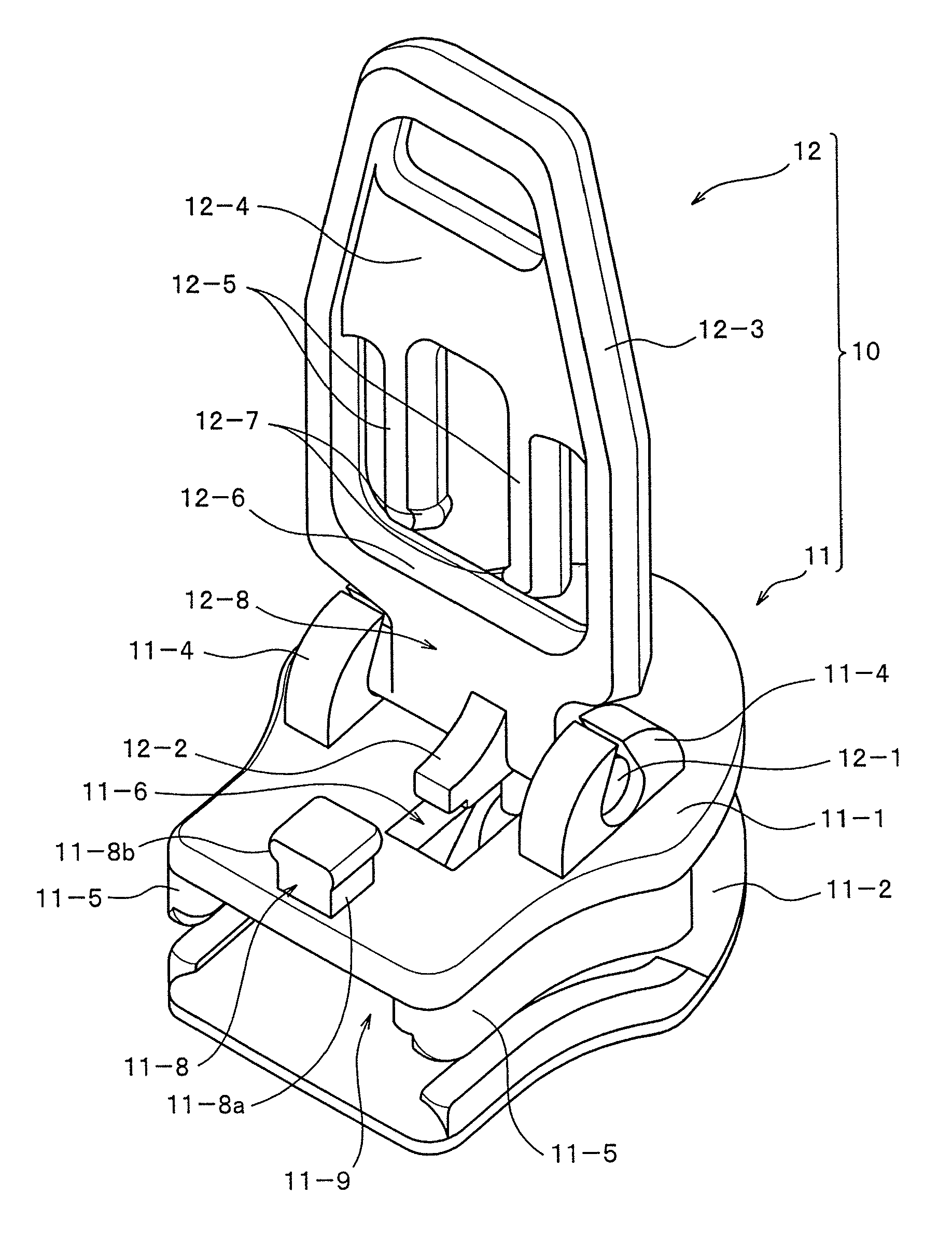
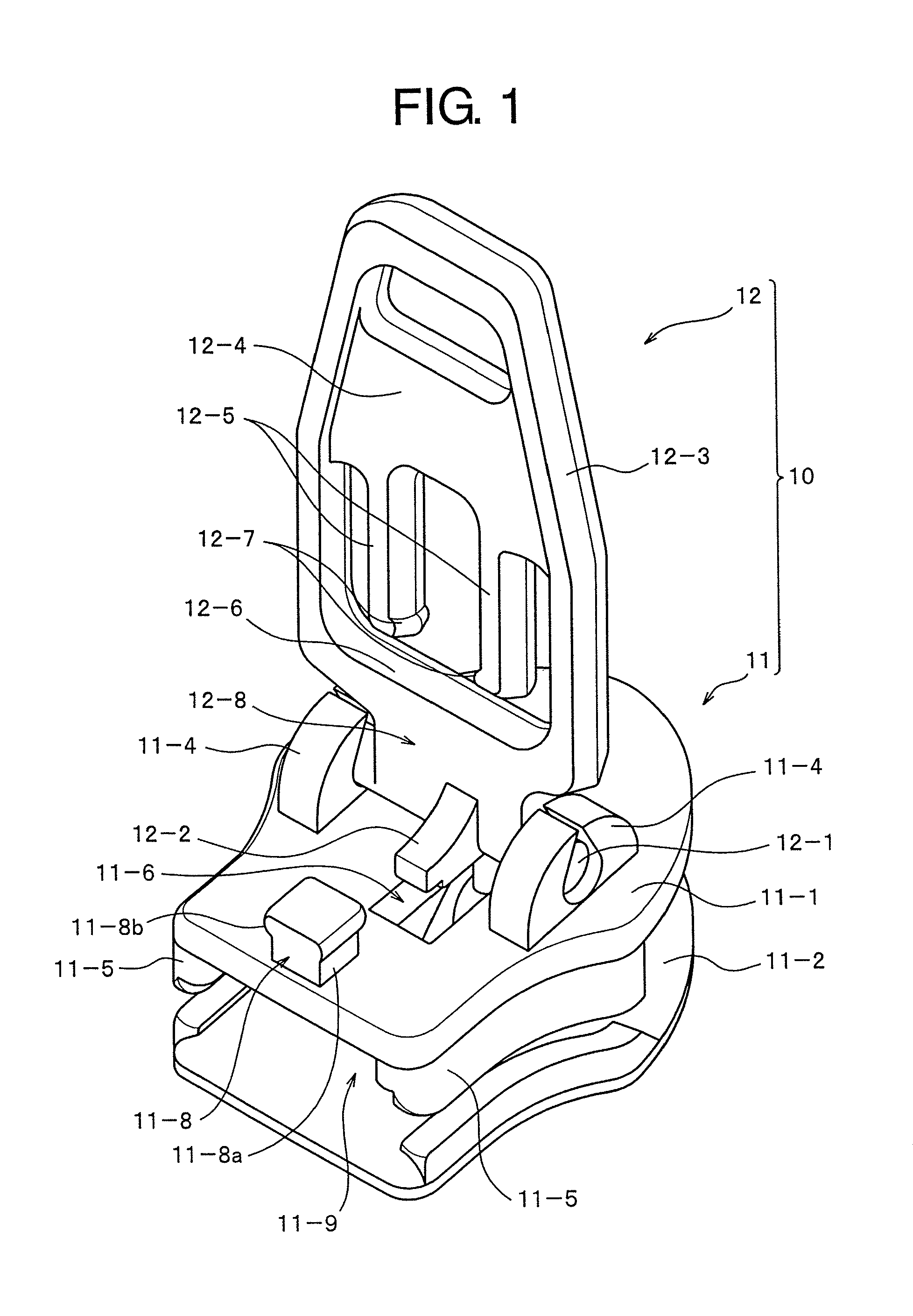
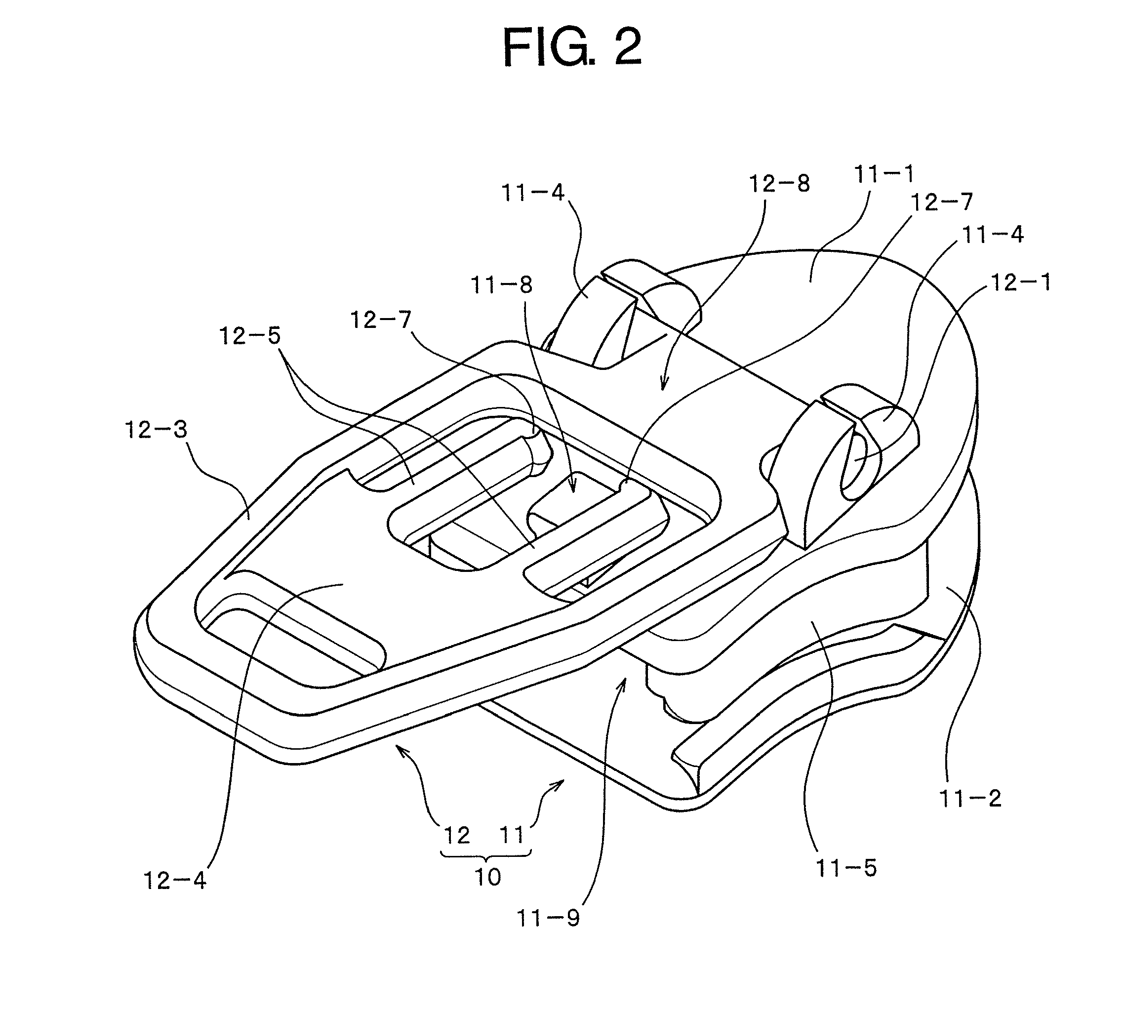
[0069]Hereinafter, preferred embodiments of the present invention will be described more in detail with reference to the accompanying drawings. FIGS. 1 to 9 illustrate a first example of the present invention. FIGS. 1 and 2 are outer appearance views of a slider 10 according to the first example. As illustrated in FIGS. 1 and 6, the slider 10 according to the first example is constructed with a slider body 11 and a handle 12.

[0070]The slider body 11 has an upper wing plate 11-1 and a lower wing plate 11-2. The shoulder-top-side end portion of the upper wing plate 11-1 and the shoulder-top-side end portion of the lower wing plate 11-2 are connected to each other with a predetermined interval by a connection column 11-3. Pivot supporting portions 11-4 for supporting a pivot shaft 12-1 of the handle 12 are configured to protrude at the left and right sides of an approximately central upper surface of the upper wing plate 11-1. Left and right flanges 11-5 are disposed in the left and ri...


PUM


Abstract

A slider for slide fastener has a handle attachment / detachment column part projected upward from an upper face of a slider body and a pair of cantilever engagement pieces formed in a window part of a handle, and they are snap-engaged. An attachment / detachment part of the cantilever engagement piece and the handle attachment / detachment column part is provided with a head storage space (PS) storing and engaging an attachment / detachment head at the time of engaging the cantilever engagement piece and the attachment / detachment head. Thus, attachment / detachment of the handle attachment / detachment column part and the cantilever engagement piece becomes easy and the cantilever engagement piece of the handle is difficult to be damaged. Uncomfortable feeling by a projected end of the handle attachment / detachment column part and hooking of fiber do not exist and durability is given.

Description

[0001]This application is a national stage application of PCT / JP2008 / 057871, which is incorporated herein by reference.TECHNICAL FIELD[0002]The present invention relates to a slider for a slide fastener capable of allowing a handle to be releasably fixed on an upper surface of the slider in a laid down state at the time of stopping the slider and capable of easily performing conversion between a stopping manipulation and a sliding manipulation of the slider.BACKGROUND ART[0003]Conventionally, as a means for engaging a slider in a closed state of a slide fastener, an engagement device is disclosed in, for example, Japanese Utility Model Application Publication (JP-Y) No. 44-21609 (Patent Document 1) or U.S. Pat. No. 2,569,076 (Patent Document 2), where an engagement protrusion is formed to protrude on an upper surface of a top stopper and an engagement hole is formed in the engagement protrusion by puncturing, where the engagement protrusion is inserted into a window hole formed in a...

Claims


Application Information

Patent Timeline
Patent Type & Authority Patents(United States)
IPC IPC(8): A44B19/26
CPCA44B19/262A44B19/305Y10T24/2586Y10T24/2568
Inventor KEYAKI, KEIICHITAKE, HIDEYA
Owner YKK CORP
Why Eureka
Try Eureka