Submersible pump

a submersible pump and sensor device technology, applied in the field of submersible pumps, can solve the problems of high design cost of the arrangement of sensor devices to detect operating variables in submersible pumps

Active Publication Date: 2013-06-04
GRUNDFOS MANAGEMENT AS
View PDF11 Cites 6 Cited by
  • Summary
  • Abstract
  • Description
  • Claims
  • Application Information

AI Technical Summary

Benefits of technology

[0005]The basic concept of the present invention is, where possible, to accommodate all the sensor devices, at least, however, one or more sensors, in a separate sensor housing which is arranged at the end of the pump, within the pump or between the motor and the pump, thus at the other end of the pump. This sensor housing may be designed in a modular manner, so that as the case may be, it may also be retrofitted to existing pumps. Also, pumps of the same series may be provided with or without a sensor housing, and thus may be delivered with and without sensor devices. Since the sensor housing is arranged between the motor and the pump, within the pump or at the end of the pump, the submersible pump by way of this is not changed with regard to is outer contour, but only with regard to its length, which is particularly important for bore-hole pumps. Since the sensor devices on the one hand are typically in connection with the delivery flow of the pump, and on the other hand with the surrounding medium, the sensor housing according to the invention is advantageously designed and arranged such that on the one hand fluid flows through it, and on the other hand it is surrounded by fluid. Thus, for example, temperatures and / or pressures of the surrounding fluid as well as of the delivered fluid may be detected. Since, where possible, the complete sensor technology or at least a large part is arranged within the sensor housing, then it is only this sensor housing, if anything, which needs to be provided with a cable leading to the outside. This is particularly advantageous with bore-hole pumps, and if the sensor housing is arranged at the upper end of the pump, only the main cable runs next to the delivery conduit. With the arrangement between the motor and the pump, there results the advantage that the cabling may be effected via the motor, which in any case requires a leading of the cable to the outside for supply of electricity and, as the case may be, also to the control and regulation electronics.
[0006]The sensor housing is advantageously divided into a fluid-leading housing part and a fluid-free housing part, and these are separated from one another by a housing wall which is preferably formed of stainless steel sheet metal. Such a housing wall may be designed comparatively thin but in an absolutely fluid-tight manner, in the manner of a can, so that with the exception of pressure sensors and / or differential pressure sensors, one may measure, for example, temperature, vibration, etc., as the case may be, also through the housing wall. This has the significant advantage that the electronics and sensor devices, which are highly sensitive to humidity, may be arranged in a reliably fluid-free housing part, whereas access to the delivery medium and / or the surrounding medium through the housing wall also exists in a practical manner.

Problems solved by technology

The arrangement of sensor devices to detect operating variables in submersible pumps is expensive with regard to the design, since on the one hand a data connection to the control and regulation electronics of the motor must exist, and on the other hand an electrical supply is necessary.
In particular with bore-hole pumps, this also represents a spatial problem, which is why the options have been to not install the sensor devices, or to install them and accept an enormous design expense.

Method used


Image

  • Submersible pump
  • Submersible pump
  • Submersible pump

Examples


Embodiment Construction

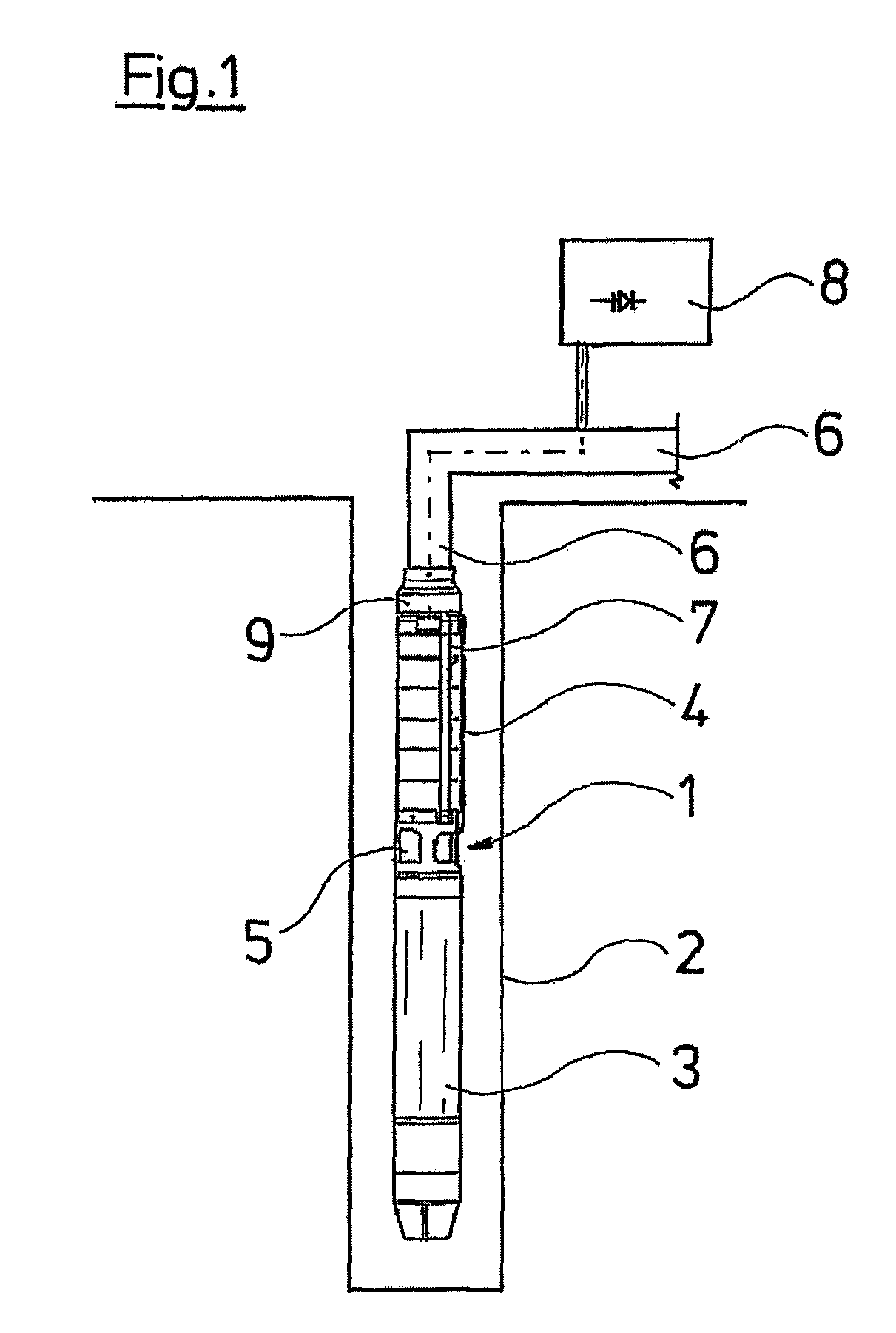
[0032]The bore-hole pump 1 represented by way of FIG. 1 is lowered into a bore-hole 2. It consists of a lower motor part 3, of which only the motor housing is visible in FIG. 1, and a multi-stage centrifugal pump 4 connects thereto to the top, whose pump stages are indicated in FIG. 1. Suction openings 5 are located between the motor 3 and the pump 4, via which the fluid located in the bore-hole 2 is sucked, delivered upwards through the multi-stage centrifugal pump 4 and finally conveyed via a pressure conduit 6 to the consumption location.

[0033]The motor 3 is supplied via a cable 7, which is led along on the outside in the region of the centrifugal pump 4, and runs next to the pressure conduit 6 to a supply and control housing 8, via which the motor is supplied with electricity. A frequency converter may for example be provided within the control housing 8, as well as all means for the control and monitoring of the pump. A sensor housing 9 whose construction is explained by way of...


PUM


Abstract

A bore-hole pump has an electrical drive motor (3) and a multi-stage centrifugal pump (4) which is driven thereby. A sensor housing (9) is arranged at the end of the pump, in which one or more sensors are arranged, and which is surrounded by fluid and through which fluid flows (FIG. 1).

Description

BACKGROUND OF THE INVENTION[0001]The invention relates to a submersible pump, in particular to a bore-hole pump. Submersible pumps are nowadays activated by frequency converters, and thus as a rule have motor electronics which render it necessary, or at least useful, to detect important operating variables of the pump, and to take these into account and process them as the case may be, on activation. Counted amongst these variables are, for example, the winding temperature of the motor, the temperature of the medium to be delivered, the delivery pressure, the ambient pressure, etc.[0002]The arrangement of sensor devices to detect operating variables in submersible pumps is expensive with regard to the design, since on the one hand a data connection to the control and regulation electronics of the motor must exist, and on the other hand an electrical supply is necessary. Furthermore, a reliable sealing with respect to the delivery medium must be ensured. In particular with bore-hole ...

Claims


Application Information

Patent Timeline
Patent Type & Authority Patents(United States)
IPC IPC(8): F04B35/04E21B47/00
CPCE21B43/128F04D13/10F04D13/08E21B47/0007E21B47/008
Inventor LYNGHOLM, JAN
Owner GRUNDFOS MANAGEMENT AS
Why Eureka
Try Eureka