Optical element, imaging optical system, and camera module

a technology of optical elements and optical systems, applied in the direction of optical elements, bundled fibre light guides, instruments, etc., can solve the problems of lens not reaching an effective screen, lens non-effective diameter area of parts, and attenuation of specular reflection light, so as to reduce ghost or flare

Active Publication Date: 2013-06-04
TIANJIN OFILM OPTO ELECTRONICS CO LTD
View PDF20 Cites 28 Cited by
  • Summary
  • Abstract
  • Description
  • Claims
  • Application Information

AI Technical Summary

Benefits of technology

[0013]Such optical element is effective for undesirable light incident from the object side at a large angle. Accordingly, it is advantageous to use the optical element as the second or third lens close to the object side as compared with using the optical element near an image forming face. The invention can be more effectively used in the optical element having a lens surface with a shape of a convex surface on the object side at least at a part in the effective diameter area of the face on the image-plane side. In addition, as a built-in camera built in a mobile apparatus such a mobile phone, in order to make it be compact and thin, it is difficult to excessively increase the number of lenses, and thus the total number of lenses including an optical element such as a filter is suppressed to preferably about at most six and seven.
[0015]With the configuration of such optical element, when the undesirable light, which is incident at an angle larger than that of light contributing to imaging, is incident to the outer peripheral face and is internally reflected thereon, a reflection direction of the reflected undesirable light is changed by the non-parallel face and thus there is no case where the undesirable light travels toward the imaging element. As a result, it is possible to reduce ghost or flare caused by the undesirable light internally reflected on the outer peripheral face to the extent as much as causing no practical problem, even though a low reflection process such as a rough face process and an ink coating process is not performed on the outer peripheral face.

Problems solved by technology

To reduce flare and ghost, a part of flange surface of a lens, is coated with ink to suppress internal reflection so that undesirable light incident to the non-effective diameter area of a part of lenses constituting the imaging optical system or the outer peripheral face of the lens does not reach an effective screen area of the imaging element due to the suppressing of the internal reflection.
However, when the undesirable light is incident from the inside to the non-effective diameter area or the outer peripheral face of the lens constituting the imaging optical system and the incident angle of the undesirable light is small and has sufficient intensity, it is difficult to attenuate the specular reflection light to the extent that there is no practical problems even when the incident face is coated with ink and is subjected to a rough face process.

Method used


Image

  • Optical element, imaging optical system, and camera module
  • Optical element, imaging optical system, and camera module
  • Optical element, imaging optical system, and camera module

Examples


Embodiment Construction

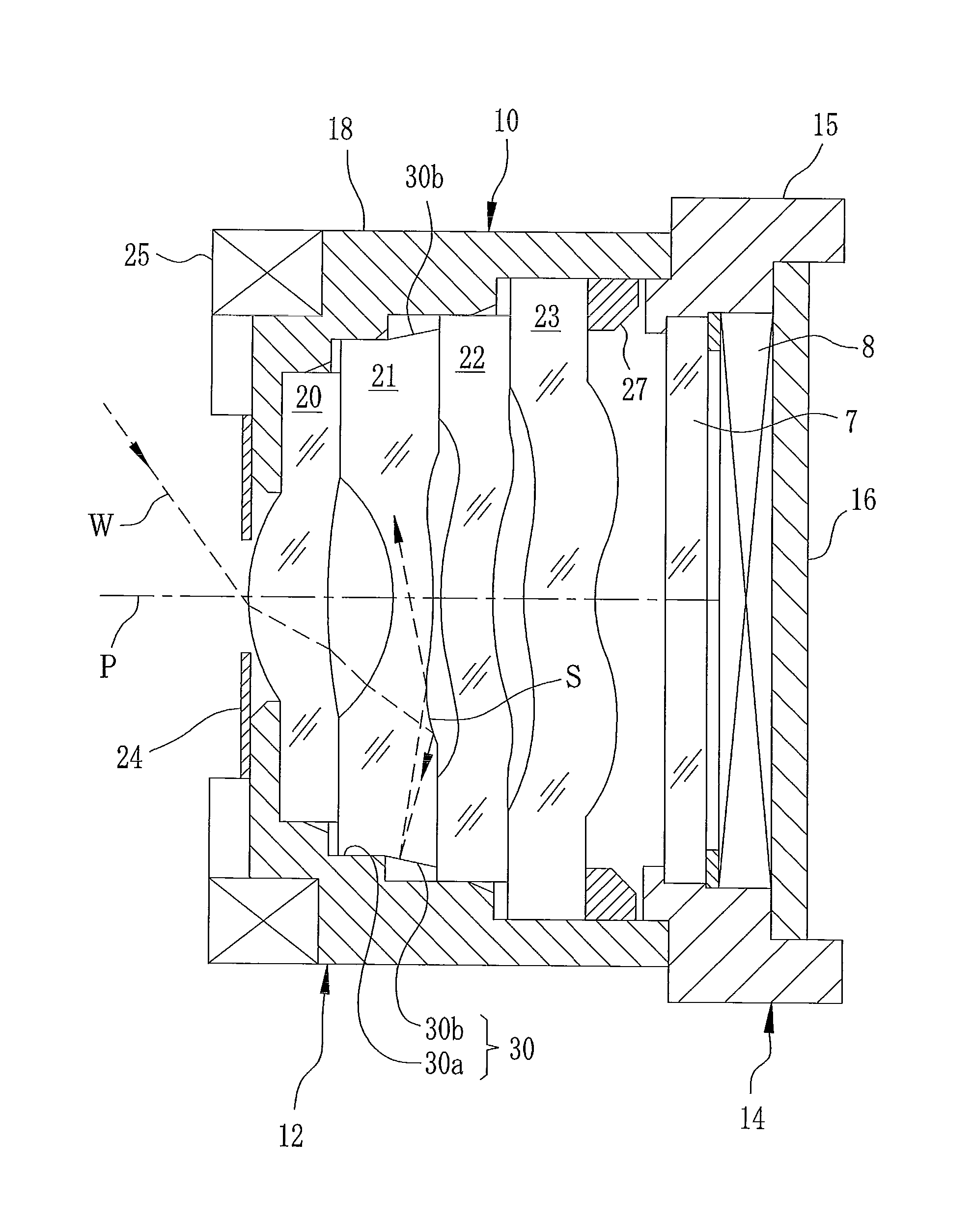
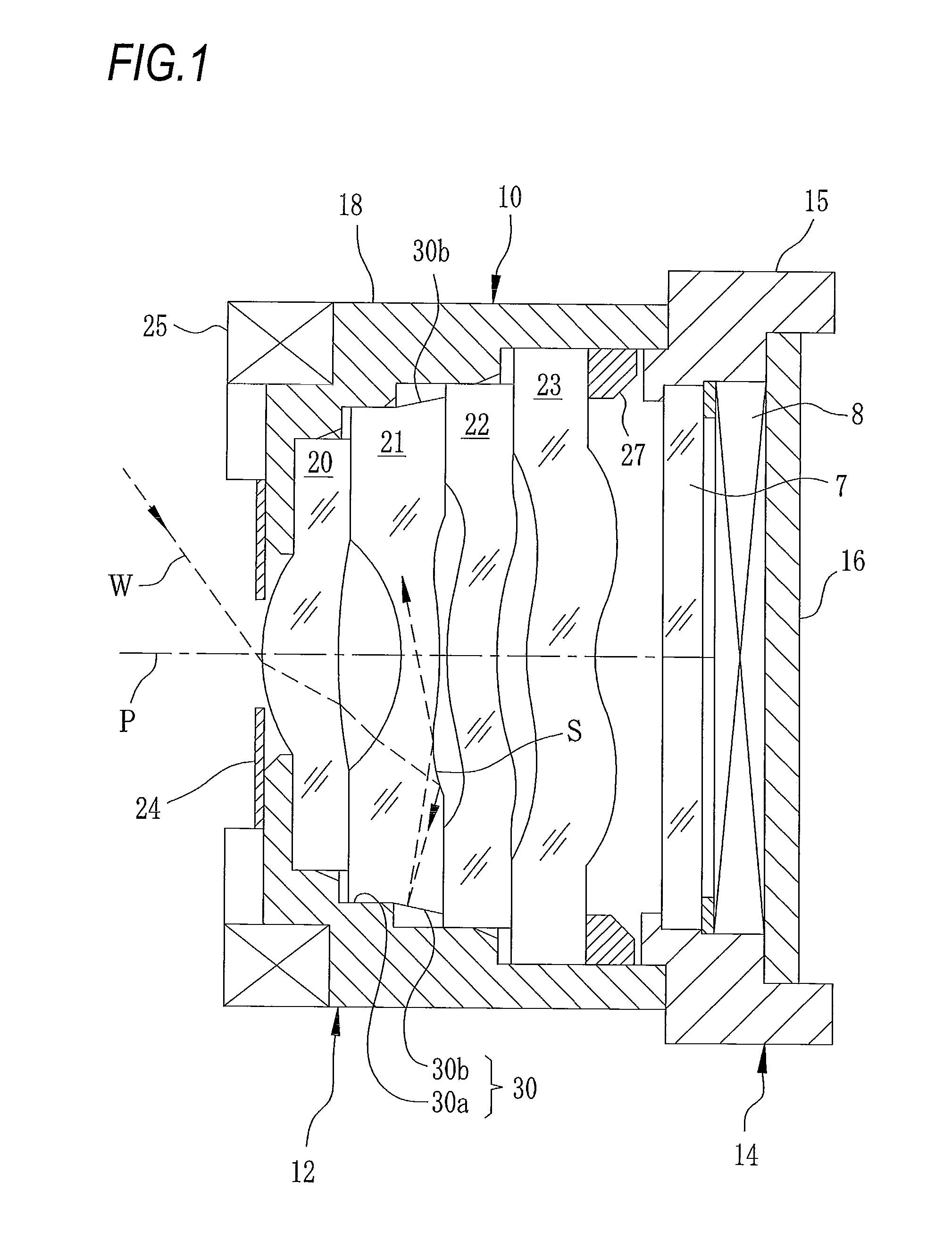
[0024]As shown in FIG. 1, a camera module 10 for a mobile phone according to the exemplary embodiment of the invention is configured by combining a lens unit 12 with an imaging unit 14, and both are integrally connected after precise positioning using a light curing adhesive or the like. The imaging unit 14 is configured by incorporating a circuit board 16 provided with a filter 7 and an imaging element 8 mounted thereon into a holder 15. A wavelength selective filter cutting ultra-violet light or infrared light or an optical low pass filter, or the like, is used as the filter 7. An IC for driving the imaging element 8, an image signal processing IC, and the like, can be mounted on the circuit board 16. In addition, the circuit board 16 is connected to a proper processing circuit through a connector, a flexible wiring board, or the like.

[0025]In the lens unit 12, a first lens 20, a second lens 21, a third lens 22, and a fourth lens 23 in this order from an object side are incorporat...


PUM


Abstract

An optical element incorporated into an imaging optical system, comprising: an effective diameter area that allows effective light flux contributing to imaging to pass, a non-effective diameter area that surrounds the effective diameter area; and an outer peripheral face that surrounds the non-effective diameter area. The effective diameter area, the non-effective diameter area and the outer peripheral face are centered on an imaging optical axis. At least a thickness-direction part of the outer peripheral face or a circumferential part thereof is a non-parallel face having an inclination to an imaging optical axis. A light incident from a face of an object side, reflected on a face of an image-plane side to the outer peripheral face and reflected on the outer peripheral face is not incident to an image plane.

Description

CROSS-REFERENCE TO RELATED APPLICATIONS[0001]This application is based on and claims priority under 35 USC 119 from Japanese Patent Application No. 2009-006588 filed on Jan. 15, 2009; the entire of which are incorporated herein by reference.BACKGROUND[0002]1. Technical Field[0003]The present invention relates to an optical element such as a lens and a filter, an imaging optical system using the optical element for a part thereof, and a camera module in which a lens unit formed by incorporating the imaging optical system into a lens barrel and an imaging unit provided with a solid state imaging element are integrally combined.[0004]2. Related Art[0005]Digital cameras are provided with a CCD or CMOS imaging element and an imaging optical system forming an optical image of a photography subject on an imaging surface of the imaging element. The imaging element is configured as an imaging unit mounted on a circuit board with IC chips for driving the imaging element or processing imaging ...

Claims


Application Information

Patent Timeline
Patent Type & Authority Patents(United States)
IPC IPC(8): H01L27/00G02B5/18H01L31/00
CPCG02B7/022G02B13/004G02B27/0018
Inventor TOMIOKA, RYOKOOKUMURA, TETSUYANODA, TAKAYUKI
Owner TIANJIN OFILM OPTO ELECTRONICS CO LTD
Why Eureka
Try Eureka