Electroluminescent device aging compensation with multilevel drive

a technology of electroluminescent devices and drive components, applied in the direction of instruments, process and machine control, light sources, etc., can solve the problem of insufficient full-color display, and achieve the effect of providing aging compensation, simple voltage measurement circuitry, and positive us

Active Publication Date: 2013-06-04
GLOBAL OLED TECH
View PDF24 Cites 0 Cited by
  • Summary
  • Abstract
  • Description
  • Claims
  • Application Information

AI Technical Summary

Benefits of technology

[0022]g) providing the black, first and second percentages to the drive circuit to cause it to provide the black, first and second current densities to the EL emitter for the black, first and second percentages, respectively, of the selected emission time, so that the integrated light output of the EL emitter during the selected emission time has an output luminance and output chromaticity colorimetrically indistinct from the designated luminance and designated chromaticity, respectively, whereby the aging of the EL emitter is compensated.
[0033]g) providing the black, first, second and third percentages to the drive circuit to cause it to provide the black, first, second and third current densities to the EL emitter for the black, first, second and third percentages, respectively, of the selected emission time, so that the integrated light output of the EL emitter during the selected emission time has an output luminance and output chromaticity colorimetrically indistinct from the designated luminance and designated chromaticity, respectively, whereby the aging of the EL emitter is compensated.
[0045]h) providing the black, first and second percentages to the drive circuit to cause it to provide the black, first and second current densities to the EL emitter for the black, first and second percentages, respectively, of the selected emission time, so that the integrated light output of the EL emitter during the selected emission time has an output luminance and output chromaticity colorimetrically indistinct from the designated luminance and designated chromaticity, respectively, whereby the aging of the EL emitter is compensated.
[0046]An advantage of this invention is an EL device that compensates for the aging of the organic materials in the device without requiring extensive or complex circuitry for accumulating a continuous measurement of light-emitting element use or time of operation. A further advantage is that it can provide aging compensation for EL devices that have only a single color of EL emitter. It is an important feature that it makes positive use of changes in chromaticity with current density which has hitherto been considered undesirable. It advantageously permits the reproduction of colors that lie off the chromaticity locus of a particular EL emitter.
[0047]It is a further advantage that it can use simple voltage measurement circuitry. It is a further advantage of various embodiments that by making all measurements of voltage, those embodiments are more sensitive to changes than methods that measure current. It is a further advantage of some embodiments that a single select line can be used to enable data input and data readout. It is a further advantage of some embodiments that characterization and compensation of EL aging are unique to the specific element and are not impacted by other elements that are open-circuited or short-circuited.

Problems solved by technology

This is not sufficient for full-color display, or for adjustable-chromaticity lamps in which the desired chromaticity may not lie on the chromaticity locus of the EL emitter.

Method used


Image

  • Electroluminescent device aging compensation with multilevel drive
  • Electroluminescent device aging compensation with multilevel drive
  • Electroluminescent device aging compensation with multilevel drive

Examples


Embodiment Construction

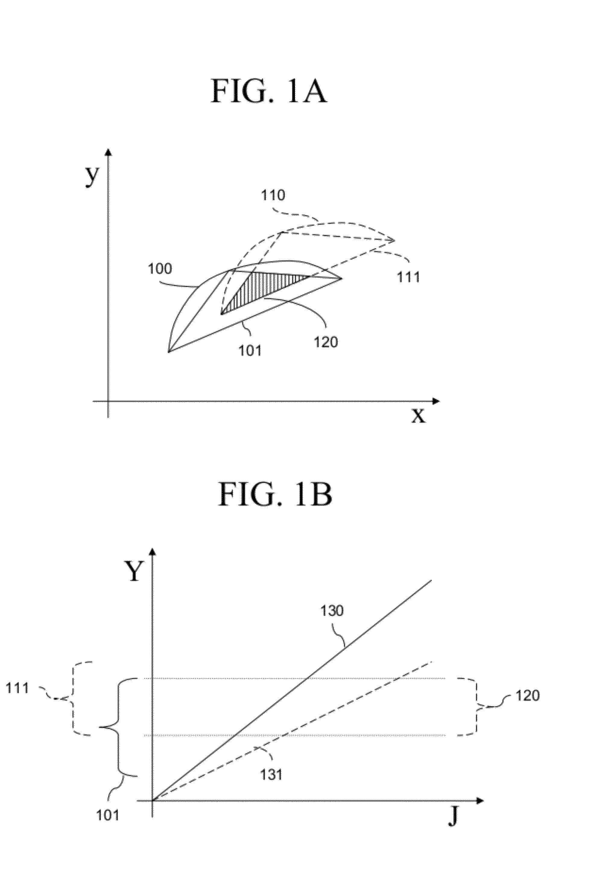
[0062]FIG. 1A shows an exemplary CIE 1931 x-y chromaticity diagram showing characteristics of an EL emitter 50 (FIG. 8) before and after aging. EL emitter 50 can be embodied in an EL device such as an EL display 10 or EL lamp. The EL emitter 50 receives current and emits light having a luminance (denoted Y) and chromaticity (x, y) that both correspond to the density of the current (J) and the age of the EL emitter 50. Curve 100 shows the chromaticities of EL emitter 50 as current density changes at a first aging level, for example new, or T100 (100% of reference efficiency). Aged curve 110 shows the chromaticities of EL emitter 50 as current density changes at a second aging level, for example end-of-life, or T50 (50% of reference efficiency). In this example, the EL emitter 50 has become more yellow over time (x and y have both increased). EL emitter 50 is preferably a broadband emitter such as a yellow or white emitter.

[0063]Three different current densities on each curve can be u...


PUM


Abstract

Compensation for aging of an electroluminescent (EL) emitter having a luminance and a chromaticity that both correspond to the density of the current and the age of the EL emitter is performed. Different black, first and second current densities are selected based on the measured age, each corresponding to emitted light colorimetrically distinct from the light emitted at the other two current densities. Respective percentages of a selected emission time are calculated for each current density to produce a designated luminance and chromaticity. The current densities are provided to the EL emitter for the calculated respective percentages of the emission time so that the integrated light output of the EL emitter during the selected emission time is colorimetrically indistinct from the designated luminance and chromaticity, no matter the age of the EL emitter.

Description

CROSS REFERENCE TO RELATED APPLICATION[0001]Reference is made to commonly-assigned, co-pending U.S. patent application Ser. No. 12 / 191,478, filed Aug. 14, 2008, entitled “OLED device with embedded chip driving” by Winters et al. and published as US 2010-0039030, commonly-assigned, co-pending U.S. patent application Ser. No. 12 / 272,222, filed Nov. 17, 2008, entitled “Compensated drive signal for electroluminescent display” by Hamer et al. and published as US 2010-0123649 and commonly assigned, co-filed U.S. Application filed by White et al., the disclosures of which are incorporated by reference herein.FIELD OF THE INVENTION[0002]The present invention relates to solid-state electroluminescent (EL) flat-panel devices, such as organic light-emitting diode (OLED) displays and lamps, and more particularly to such devices having means to compensate for the changes in performance with use of the electroluminescent device components.BACKGROUND OF THE INVENTION[0003]Electroluminescent (EL) d...

Claims


Application Information

Patent Timeline
Patent Type & Authority Patents(United States)
IPC IPC(8): G09G3/30G09G3/10
CPCG09G3/30G09G3/3208G09G2320/0242G09G2320/0666G09G2320/0693G09G2320/048G09G2320/043G09G2330/021
Inventor WHITE, CHRISTOPHER J.
Owner GLOBAL OLED TECH
Why Eureka
Try Eureka