System and method for the display of a ballestic trajectory adjusted reticule

a technology of trajectory adjustment and display system, which is applied in the field of system and method for the display of ballestic trajectory adjusted display system, can solve the problem of inability to determine with certainty where to aim/orient the weapon system, and achieve the effect of long duration operation time and low power consumption

Active Publication Date: 2013-06-11
AWIS LLC
View PDF4 Cites 14 Cited by
  • Summary
  • Abstract
  • Description
  • Claims
  • Application Information

AI Technical Summary

Benefits of technology

[0019]The system operates at low voltage, conserving energy for a long duration operational time.

Problems solved by technology

A concern, which many law enforcement, armed forces, or security personnel may encounter during a firearm confrontation, is the inability to determine with certainty where to aim / orient the weapon system in order to guarantee a fit on the target with the first shot.

Method used


Image

  • System and method for the display of a ballestic trajectory adjusted reticule
  • System and method for the display of a ballestic trajectory adjusted reticule
  • System and method for the display of a ballestic trajectory adjusted reticule

Examples


Embodiment Construction

[0028]Reference will now be made in detail to the preferred embodiments of the present invention, examples of which are illustrated in the accompanying drawings.

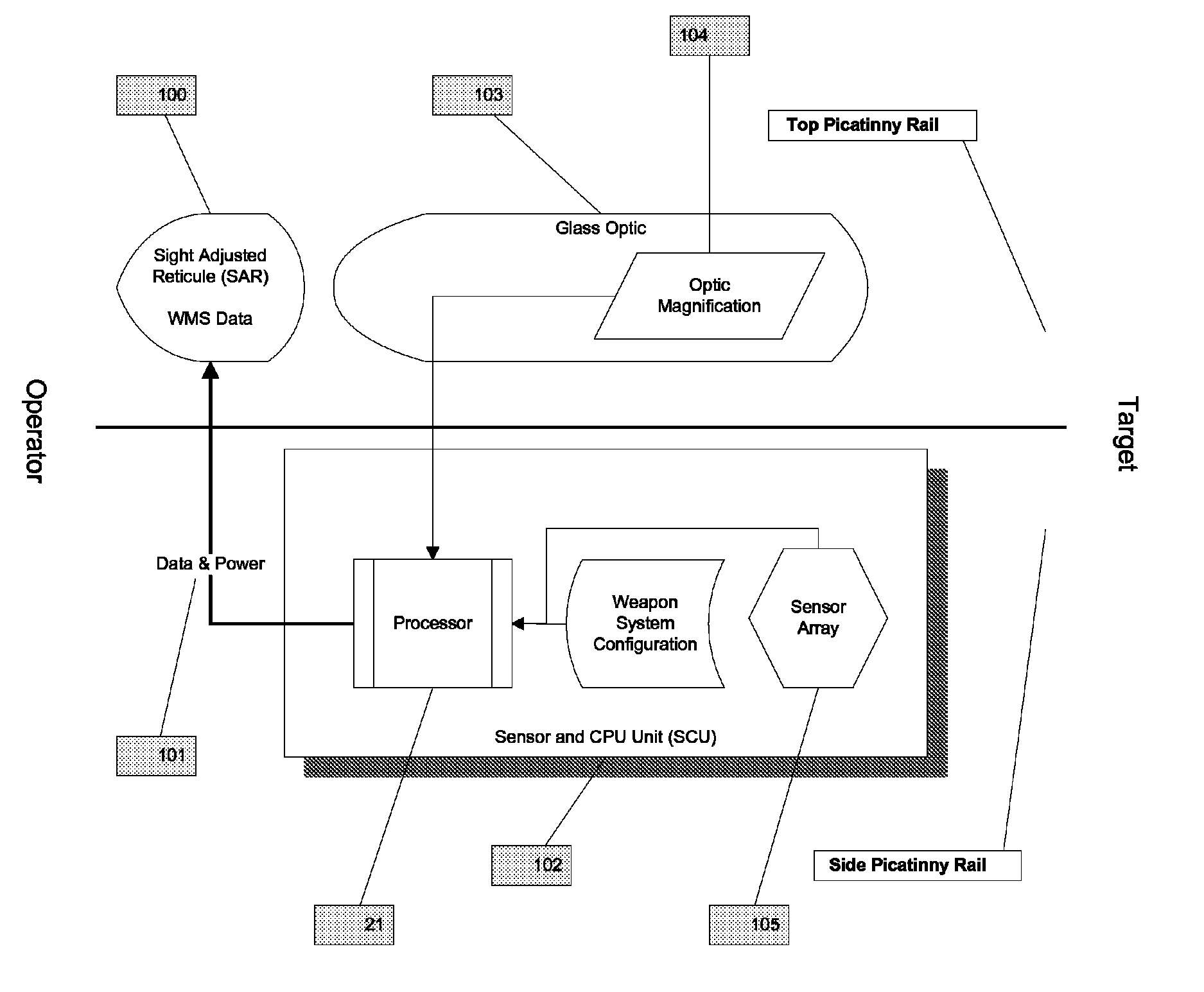
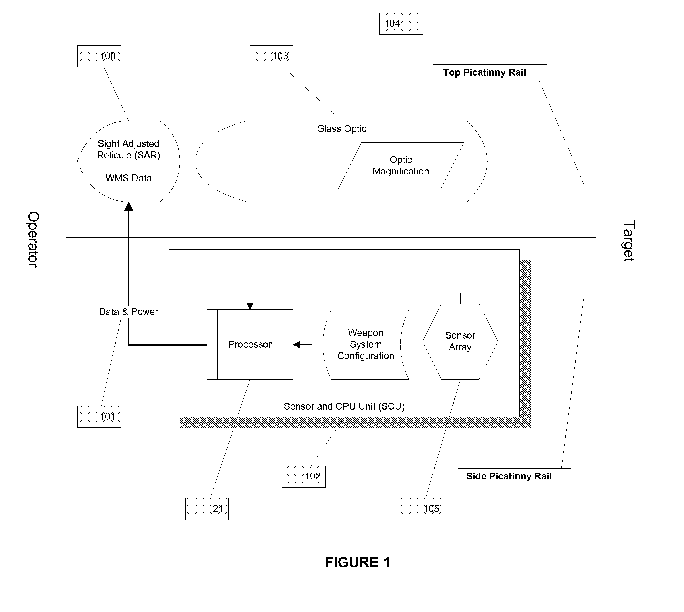
[0029]The Sight Adjusted Reticule (SAR) consists of a mounting solution and frame to house the transparent display. The housing and display are provided with power and a display signal either via a physical connection to the Sensor and CPU Unit (SCU) or an independent (integrated) power source and wireless data-display connection.

[0030]FIG. 1 shows one exemplary Sight Adjusted Reticule (SAR) 100 in accordance with the preferred embodiment. The SAR is attached to the top (12 o′clock) Picatinny / accessory rail, in front of any glass optic 103 that might be attached to the weapon system. In one exemplary configuration, data and power are provided to the SAR 100 via a wired connection 101 between the SAR and the Sensor and CPU Unit (SCU) 102. The SCU 102 also contains configuration information for the system and processes inputs ...


PUM


Abstract

This invention relates to a method, system and computer program product that calculates a real-time, accurate, firing solution for man carried weapon system; specifically a transparent display to be located in-line with a weapon mounted optic and a device to adjust the aim point through real-time data collection, analysis and real-time visual feedback to the operator. A firing solution system mounted on a projectile weapon comprising: A Sensor and CPU Unit (SCU) and a Sight Adjusted Reticule (SAR) and a PC Dongle which configured to facilitate communication between the SCU and a personal computer (PC), or similar computing device, enabling management of the SCU configuration and offloading of sensor obtained and system determined data values.

Description

CROSS-REFERENCE TO RELATED APPLICATION[0001]This application is a non-provisional application of U.S. Provisional Patent Application No. 61 / 378363, filed Aug. 30, 2010, entitled “System for the real time adjustment of the aim point for a designated target and display of secondary data”, which is incorporated by reference herein in its entirety.BACKGROUND OF THE INVENTION[0002]1. Field of Invention[0003]This invention relates to a method, system and computer program product that allows for the real-time adjustment of the sight reticule of a firearm by using a transparent display; optionally in combination with a magnified or non-magnified optic.[0004]2. Background of Related Art[0005]A concern, which many law enforcement, armed forces, or security personnel may encounter during a firearm confrontation, is the inability to determine with certainty where to aim / orient the weapon system in order to guarantee a fit on the target with the first shot.[0006]At the lack of an adequate automa...

Claims


Application Information

Patent Timeline
Patent Type & Authority Patents(United States)
IPC IPC(8): G06G7/80
CPCF41G1/473F41G3/06
Inventor ARBOUW, PAUL
Owner AWIS LLC
Why Eureka
Try Eureka