Card insert/eject mechanism having a position-limiting plate engaging a sliding block

a position-limiting plate and card inserting technology, applied in the direction of coupling parts engagement/disengagement, coupling device connection, instruments, etc., can solve the problems of low structural strength of the card inserting/ejecting mechanism of the push-push connector described above, and the connection between the connector and the electronic card inserted therein is not secure enough, so as to minimize the chances of malfunction. , the effect of simple structur

Inactive Publication Date: 2013-06-11
GUIMA SCI & TECH
View PDF4 Cites 5 Cited by
  • Summary
  • Abstract
  • Description
  • Claims
  • Application Information

AI Technical Summary

Benefits of technology

[0007]In view of the various drawbacks of the card insert / eject mechanism of the conventional card connectors, the inventor of the present invention put years of practical experience into research and design and finally succeeded in developing a card insert / eject mechanism for use in a card connector. The card insert / eject mechanism disclosed herein allows a user to connect an electronic card firmly to a card connector and features a simple structure that minimizes the chances of malfunction.
[0011]The foregoing card insert / eject mechanism has high structural strength, solves the problem of insecure card engagement typical of the conventional push-push connectors, and dispenses with the easy-to-get-stuck and easy-to-get-loose positioning pin commonly used in the conventional connectors.
[0016]The resilient element is provided in the track groove and applies a force to the rear end of the sliding block to bias the sliding block toward the front end of the insulating seat. Hence, driven by the resilient element, the pushing portion can push the tray out of the receiving space. The release bar, which is disposed in the track groove, has one end adjacent to the bar hole and the other end adjacent to the front end of the sliding block. When the release bar is pushed toward the sliding block, the release bar pushes the position-limiting resilient plate and thereby disengages the aforesaid end thereof from the front end of the lifting portion, allowing the resilient element to push sliding block against the release bar. Consequently, the tray is driven toward the front end of the insulating seat, causing the position-limiting resilient plate to press against the top surface of the lifting portion again. As soon as the external force applied to the release bar is removed, the resilient element pushes the sliding block, which in turn pushes the release bar and the tray. Thus, the tray is pushed out of the receiving space, and the user can now remove the electronic card from the card cavity. In the two-stage releasing process described above, the resilient force of the resilient element is kept from being released all at once; therefore, the tray will not throw the electronic card out of the card cavity as may otherwise occur if the tray, under full force of the resilient element, dashes out through the card insertion slot.
[0017]The card insertion slots of some conventional card connectors are directly exposed on the surface of an electronic device and may therefore compromise the appearance of the electronic device. Besides, dust may easily enter a conventional card connector through the card insertion slot if there is no electronic card inserted therein. To solve these two problems, some manufacturers designed a cover for covering, and thereby preventing the entry of dust into, a card insertion slot while giving an integrated look to an electronic device having the card insertion slot. Nevertheless, the opening and closing of such a cover can be difficult and annoying, simply considering the fact that both electronic devices and electronic cards are made increasingly smaller. By contrast, the card connector proposed by the present invention can be so designed that the tray and the release bar match the exterior of an electronic device and therefore will not impair the overall look of the electronic device. In addition, the tray, once pushed in place, can keep off dust regardless of whether there is an electronic card in the tray. The configurations of the tray and the release bar also make easy the insertion and ejection of electronic cards.

Problems solved by technology

However, the card insert / eject mechanism of the push-push connector described above still has its drawbacks.
First of all, the card insert / eject mechanism has low structural strength.
More specifically, the connection between the connector and the electronic card inserted therein is not secure enough.
Should it happen without the user knowing it, the electronic card may simply get lost.
Moreover, the positioning pin, when moved along the positioning track, is very likely to get stuck in the track or come loose, thus hindering card insertion or ejection.
As the connector is installed in an electronic device and is open to the outside only through the card insertion slot, it is difficult to perform maintenance work on the connector.
In fact, the electronic device must be opened in order to troubleshoot the connector, which is extremely inconvenient.

Method used


Image

  • Card insert/eject mechanism having a position-limiting plate engaging a sliding block
  • Card insert/eject mechanism having a position-limiting plate engaging a sliding block
  • Card insert/eject mechanism having a position-limiting plate engaging a sliding block

Examples


Embodiment Construction

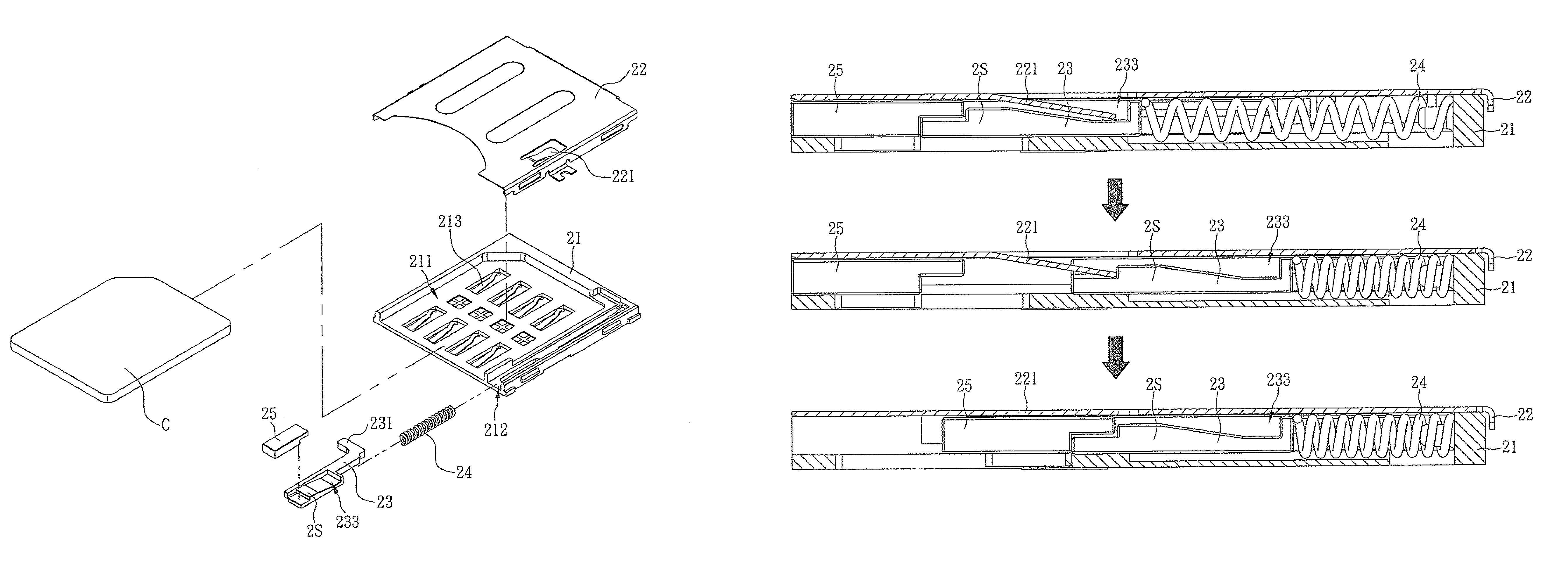
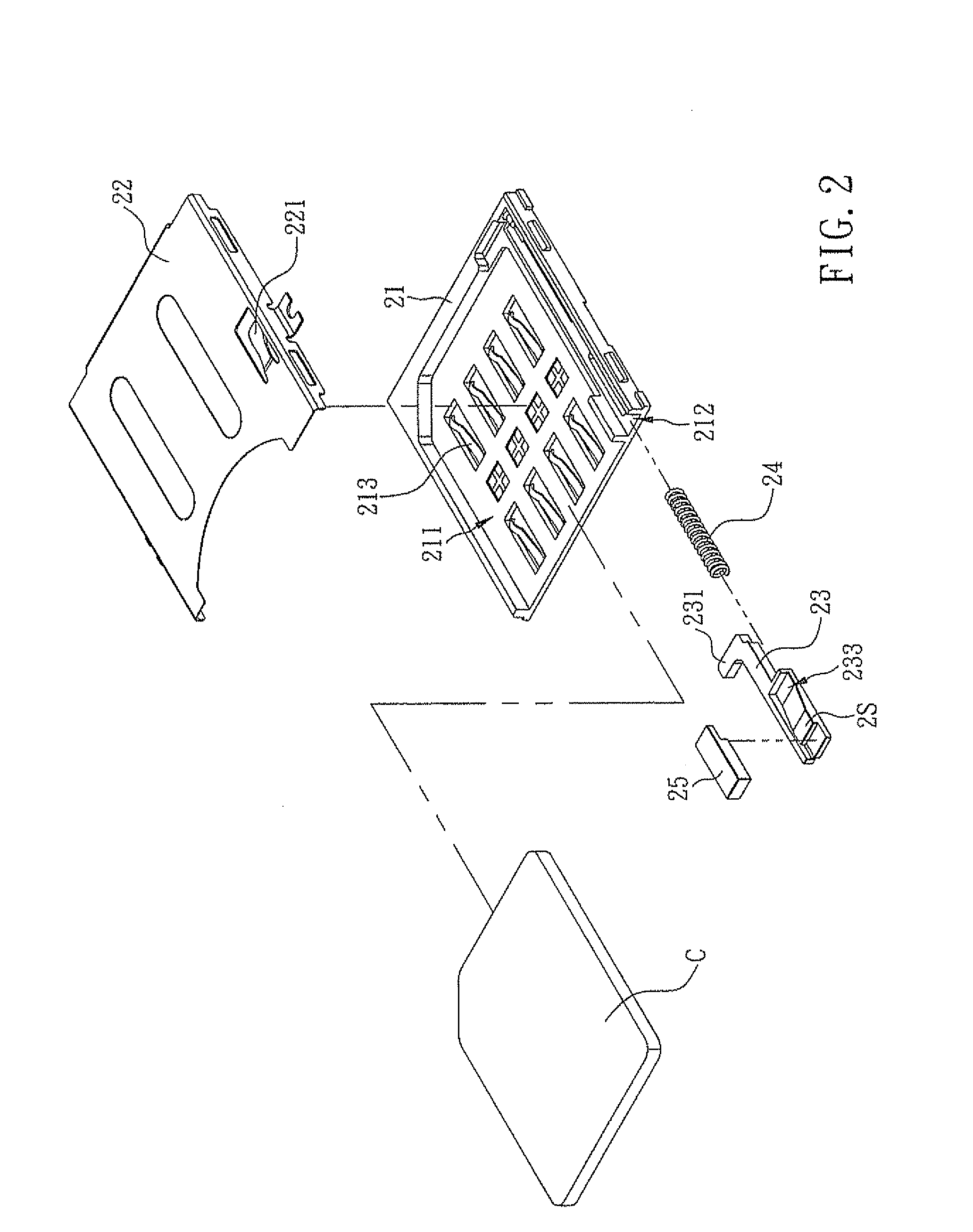
[0026]The present invention discloses a card insert / eject mechanism of a card connector. More particularly, the card insert / eject mechanism is applicable to a card connector of an electronic device. Referring to FIG. 2, a mechanism according to the first preferred embodiment of the present invention includes an insulating seat 21, a metal housing 22, a sliding block 23, a resilient element 24, and a release bar 25. The insulating seat 21 is formed with a receiving space 211 and a track groove 212. A plurality of signal terminals 213 are distributed over an inner bottom surface of the insulating seat 21 that corresponds in position to the receiving space 211. The track groove 212 is adjacent to a lateral side of the receiving space 211. The metal housing 22 is connected to the insulating seat 21 to form a single piece and thereby cover the top of the receiving space 211 and the top of the track groove 212; consequently, the receiving space 211 and the track groove 212 form a card ins...


PUM


Abstract

The present invention is to provide a card insert / eject mechanism, which includes an insulating seat formed with a receiving space and a track groove; a metal housing covering the receiving space and track groove and having a position-limiting resilient plate at a bottom surface thereof; a sliding block slidable along the track groove and laterally provided with a pushing portion that extends into the receiving space thereby, when an electronic card pushes the pushing portion, the sliding block is moved against rear end of the insulating seat; a resilient element provided in the track groove for applying a force to rear end of the sliding block; and a release bar disposed in the track groove for releasing the position-limiting resilient plate and enabling the sliding block to push the electronic card out of the receiving space, so as to effectively solve the insecure card engagement problem in conventional push-push connectors.

Description

FIELD OF THE INVENTION[0001]The present invention relates to a card connector, more particularly to a card connector having a card insert / eject mechanism installed therein, so as to enhance structural strength thereof, solve the problem of insecure card engagement typical of conventional push-push connectors, and dispense with an easy-to-get-stuck and easy-to-get-loose positioning pin commonly used in the conventional push-push connectors.BACKGROUND OF THE INVENTION[0002]With the rapid development of information technology and of the electronic industry, consumer electronics are now evolving from one generation to the next on a regular basis. Some notable examples of such electronic products are digital still cameras, digital recorders, smart phones, digital game consoles, laptop computers, personal digital assistants (PDAs), and digital file players. These electronic products are available not only in a variety of types but also at more and more affordable prices, so that consumers...

Claims


Application Information

Patent Timeline
Patent Type & Authority Patents(United States)
IPC IPC(8): H01R13/62
CPCG06K13/08H01R13/635
Inventor LEE, YI-MINGLEE, CHIEN-YEH
Owner GUIMA SCI & TECH
Why Eureka
Try Eureka