Stereoscopic glasses

a stereoscopic and glasses technology, applied in the field of three-dimensional image display systems, can solve the problems of difficult to stably set the stereoscopic glasses in position, difficult to perform stable stereoscopic operation of three-dimensional images, and difficulty in putting on stereoscopic glasses, and achieve the effect of stable stereoscopic operation and easy to wear

Inactive Publication Date: 2013-06-11
SONY CORP
View PDF29 Cites 1 Cited by
  • Summary
  • Abstract
  • Description
  • Claims
  • Application Information

AI Technical Summary

Benefits of technology

[0010]It is therefore desirable to provide a pair of stereoscopic glasses that can advantageously allow for stable stereoscopic operation and can be easily worn even over already-worn glasses.
[0011]According to an embodiment of the present invention, there is provided a pair of stereoscopic glasses including a pair of left and right stereoscopic rims connected to each other and respectively holding stereoscopic optical components used when observing a stereoscopic image, and a stereoscopic frame that includes stereoscopic temples extending rearward from the stereoscopic rims. The stereoscopic frame is provided with an engagement section that is brought into engagement with a rim or a bridge of a frame of glasses already worn by a user in a state where the stereoscopic optical components are positioned in front of lenses of the glasses so that the stereoscopic optical components are positionally maintained in front of the lenses of the glasses.

Problems solved by technology

Therefore, not only is it difficult to put on the stereoscopic glasses, but it is also difficult to stably set the stereoscopic glasses in position.
Thus, the stereoscopic optical components of the stereoscopic glasses tend to shift from a position in front of the lenses of the already-worn glasses, resulting in a difficulty in performing stable stereoscopic operation of three-dimensional images.

Method used


Image

  • Stereoscopic glasses
  • Stereoscopic glasses
  • Stereoscopic glasses

Examples


first embodiment

[0040]A first embodiment of the present invention will now be described with reference to FIGS. 1A to 3C.

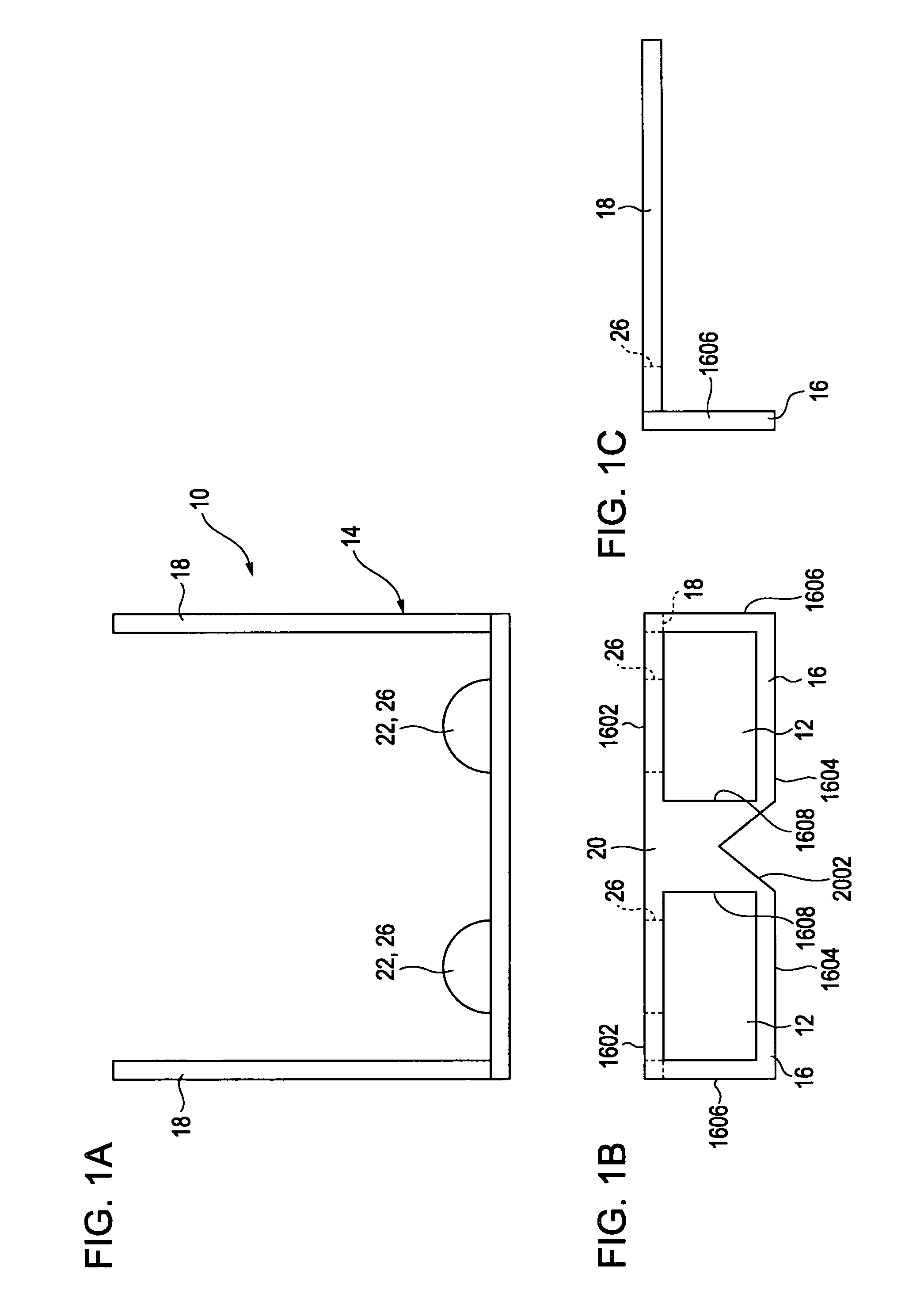
[0041]Referring to FIGS. 1A, 1B, and 1C, a pair of stereoscopic glasses 10 includes a pair of left and right stereoscopic optical components 12 and a frame 14 that holds these stereoscopic optical components 12.

[0042]The stereoscopic optical components 12 are thin rectangular plates of the same shape and size.

[0043]The stereoscopic optical components 12 are to be used when observing a stereoscopic image.

[0044]Specifically, the stereoscopic optical components 12 are used for performing stereoscopic operation by independently guiding an image for the left eye to the left eye and an image for the right eye to the right eye.

[0045]Examples of stereoscopic optical components 12 include two liquid-crystal shutters that can be driven between transparent and nontransparent modes, two polarizing filters (i.e., polarizing plates) with different polarization directions, and two wavelength-se...

second embodiment

[0078]A second embodiment of the present invention will now be described with reference to FIGS. 4A to 5C. The sections and components in this embodiment that are similar to those in the first embodiment are given the same reference numerals, and therefore, the descriptions of those sections and components will not be repeated.

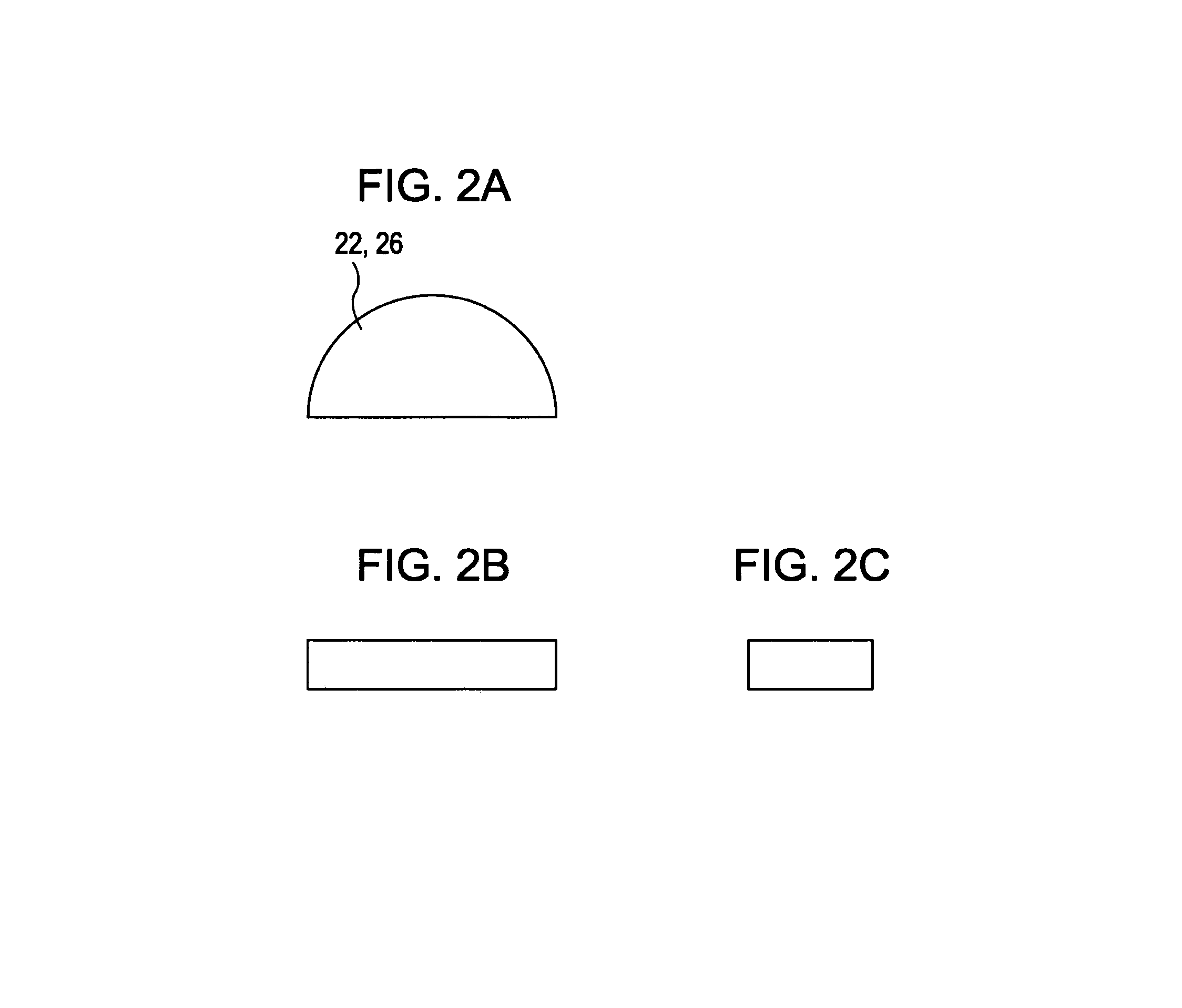
[0079]The second embodiment is a modification of the first embodiment and differs from the first embodiment in that the stopper segments 26 are provided with projections 28, as shown in FIGS. 4A, 4B, and 4C.

[0080]The projections 28 are each provided at an end of the corresponding stopper segment 26 most distant from the upper rim segment 1602 of the corresponding stereoscopic rim 16, that is, a rear end of the stopper segment 26.

[0081]The projections 28 can be secured to the rims 4A of the frame 4 of the glasses 2 or to the lenses 6 held by these rims 4A. By securing the projections 28 to the rims 4A or the lenses 6, forward movement of the stereoscopic optica...

third embodiment

[0084]A third embodiment of the present invention will now be described with reference to FIGS. 6A to 6C.

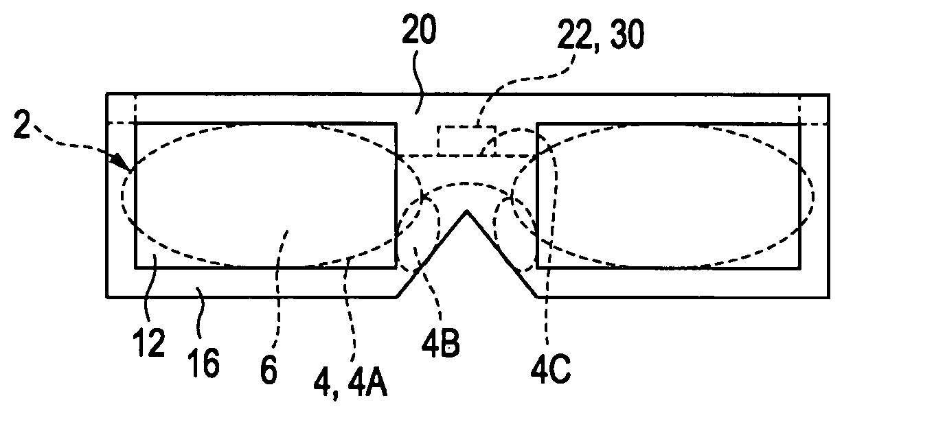
[0085]As shown in FIGS. 6A, 6B, and 6C, the third embodiment differs from the first embodiment in that the engagement section 22 is included in the stereoscopic bridge 20.

[0086]The engagement section 22 includes a stopper segment 30 that protrudes rearward from the stereoscopic bridge 20 and that can be placed on a bridge 4C of the frame 4 of the glasses 2 from above.

[0087]The stopper segment 30 and the stereoscopic bridge 20 are formed as a single unit.

[0088]As shown in FIGS. 6A, 6B, and 6C, the stopper segment 30 has a convex shape that protrudes rearward, and the midsection thereof in the left-right width direction is the most rearward protruding section.

[0089]The stopper segment 30 protrudes rearward by a length that prevents the stereoscopic glasses 10 from touching the user's eyelids when the stereoscopic glasses 10 are worn by a user not wearing glasses. In other words, th...


PUM


Abstract

A pair of stereoscopic glasses includes a pair of left and right stereoscopic rims connected to each other and respectively holding stereoscopic optical components used when observing a stereoscopic image, and a stereoscopic frame that includes stereoscopic temples extending rearward from the stereoscopic rims. The stereoscopic frame is provided with an engagement section that is brought into engagement with a rim or a bridge of a frame of glasses already worn by a user in a state where the stereoscopic optical components are positioned in front of lenses of the glasses so that the stereoscopic optical components are positionally maintained in front of the lenses of the glasses.

Description

CROSS-REFERENCE TO RELATED APPLICATION[0001]The present application claims priority from Japanese Patent Application No. JP 2009-003691 filed in the Japanese Patent Office on Jan. 9, 2009, the entire content of which is incorporated herein by reference.[0002]The present invention relates to stereoscopic glasses.BACKGROUND OF THE INVENTION[0003]1. Field of the Invention[0004]2. Description of the Related Art[0005]In the related art, three-dimensional image display systems use a stereoscopic image projector to project an image for the left eye and an image for the right eye onto a screen so that a user wearing a pair of stereoscopic glasses can observe a stereoscopic image on the screen.[0006]Examples of such stereoscopic glasses are provided by Japanese Unexamined Patent Application Publications Nos. 11-75223, 11-95186, and 11-98537. Specifically, in these examples, a pair of stereoscopic glasses includes a pair of left and right stereoscopic rims connected to each other and respecti...

Claims


Application Information

Patent Timeline
Patent Type & Authority Patents(United States)
IPC IPC(8): H04N13/04G02B30/22G02B30/25
CPCG02C5/001G02C5/008G02C5/006G02B27/22G02C2200/12H04N2213/001H04N2213/008G02B30/22
Inventor ARAI, HIDEKI
Owner SONY CORP
Why Eureka
Try Eureka