Universal coaxial cable compression tool

a universal, coaxial cable technology, applied in the direction of manufacturing tools, coupling device connections, insulating conductors/cables, etc., to achieve the effect of reliable and efficien

Active Publication Date: 2013-06-18
PPC BROADBAND INC
View PDF14 Cites 9 Cited by
  • Summary
  • Abstract
  • Description
  • Claims
  • Application Information

AI Technical Summary

Benefits of technology

[0006]It is therefore an object to provide for a novel and improved crimping tool conformable for use in compressing different sizes and lengths of fittings onto the end of a cable in a reliable and efficient manner.
[0007]Another object is to provide for a novel and improved hand-held crimping tool for crimping fittings into sealed engagement with a coaxial cable without requiring a preassembled crimping ring but is capable of achieving a uniform seal notwithstanding differences in length of the fitting, or to compensate for the presence of wear or dirt and differences in manufacturing tolerances.
[0008]A further object is to provide for a novel and improved hand-held crimping tool for terminating cable ends without the use of a preassembled crimping ring which greatly facilitates both mounting and release of the cable end before and after the crimping operation and wherein the tool is lightweight but sturdy and requires a minimum number of parts.
[0011]Another feature is that different sets of die members can be interchangeably mounted in the die housing according to the size and length of fitting to be crimped onto the cable end, and each set of die members defines a cavity having a first diameter corresponding to an outer diameter of the sleeve portion and a second diameter which corresponds to the outer diameter of the cable end. The housing itself is characterized by having inclined guideways on opposite sides of the housing to advance the die members between the expanded and contracted positions. The inclined guideways include end portions which increase the compressive force exerted by the die members on the sleeve portions in completing the crimping operation and are self-compensating for any manufacturing variance or wear of the die cavities and guide portions of the die members.
[0013]Alternate embodiments have been devised in which a compression tool is of the type hereinbefore described but includes an extension tip releasably connected to one end of the plunger to compensate for variations in length of the cable fitting to be crimped or terminated on the cable end, and the guideways on opposite sides of the tool are enlarged and provided with forward and rearward spaced, inclined guide portions to control slidable movement of the die members between the expanded and contracted positions so as to be conformable for use with a wide range of different diameter fittings. In this relation, by enlarging opposite sides of the tool, it is possible to form larger openings in the sides to gain access to the plunger for the purpose of insertion and removal of the extension tip. Further, in order to accommodate mini-coaxial cable fittings in the same compression tool as standard sized fittings, a plastic insert is interposed between the inner and outer concentric sleeve members of the fitting in order to compensate for the reduced thickness of the jacket end portion of the cable inserted between the concentric sleeve members as a preliminary to crimping.

Problems solved by technology

In the past, however, when the die portions have been mounted on the body of the tool they are difficult to open when the fitting becomes jammed; also the ability of the die halves to resist misalignment when subjected to crimping forces; and the ability of the tool to be self-adjusting for wear tolerances and other slight differences in size and length of each fitting or connector have presented problems in the field.

Method used


Image

  • Universal coaxial cable compression tool
  • Universal coaxial cable compression tool
  • Universal coaxial cable compression tool

Examples


Embodiment Construction

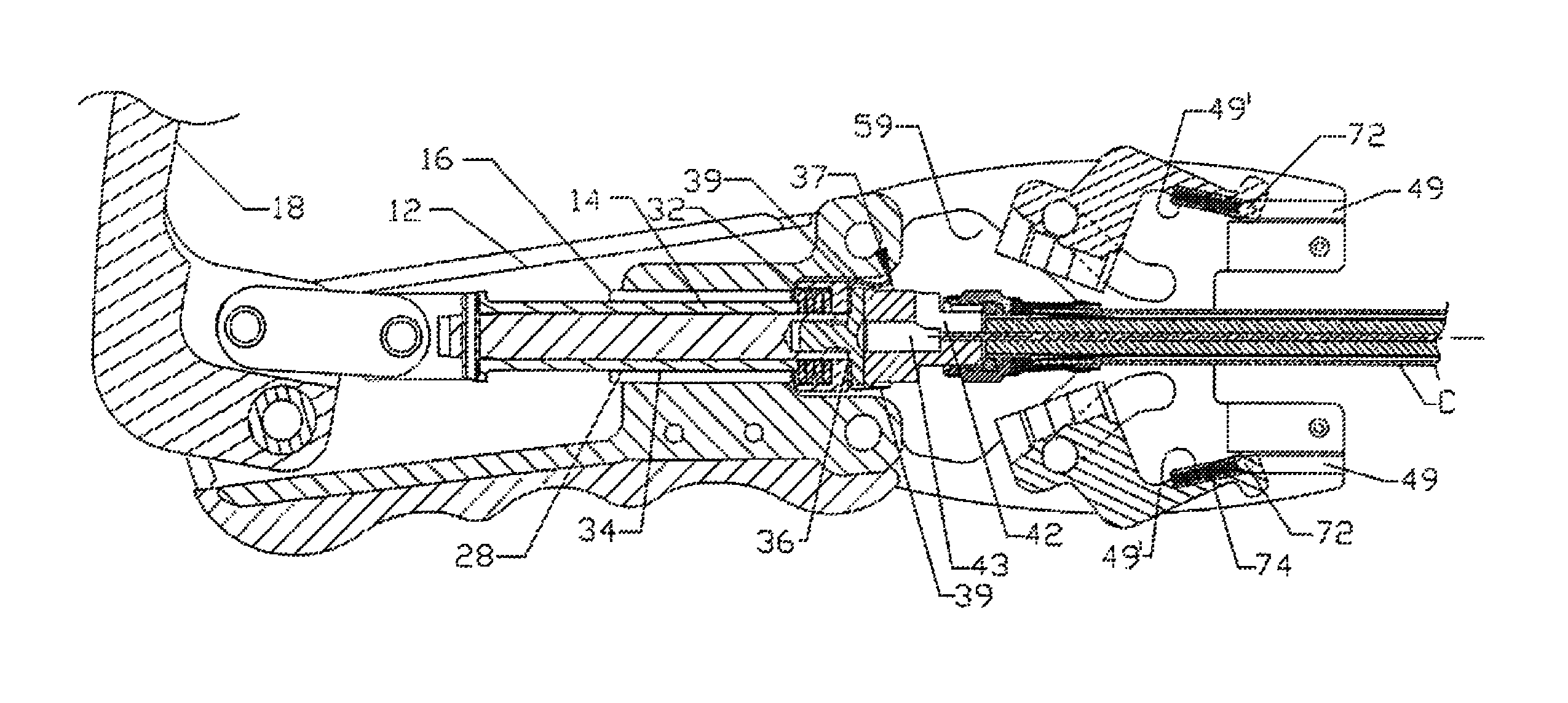
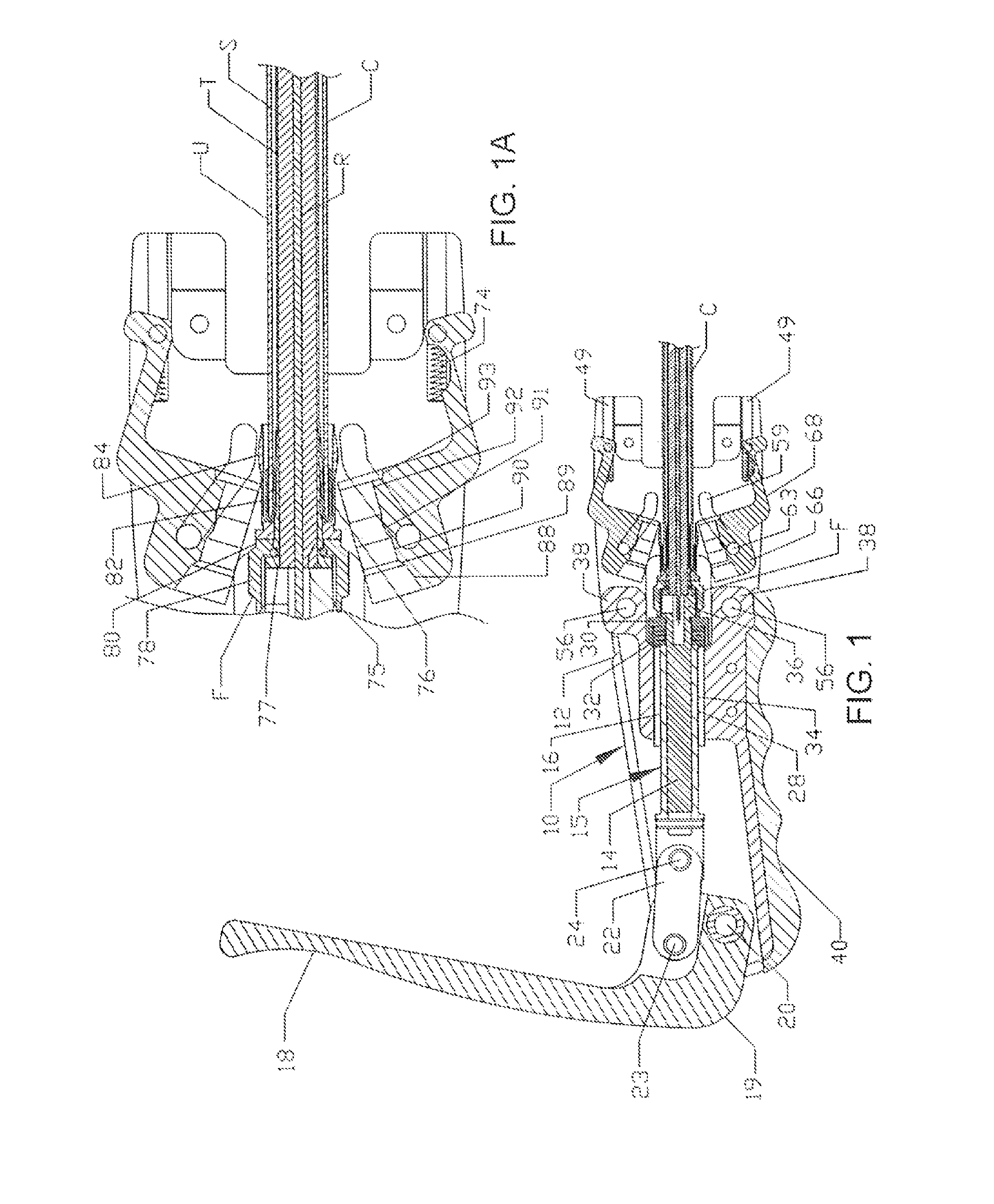
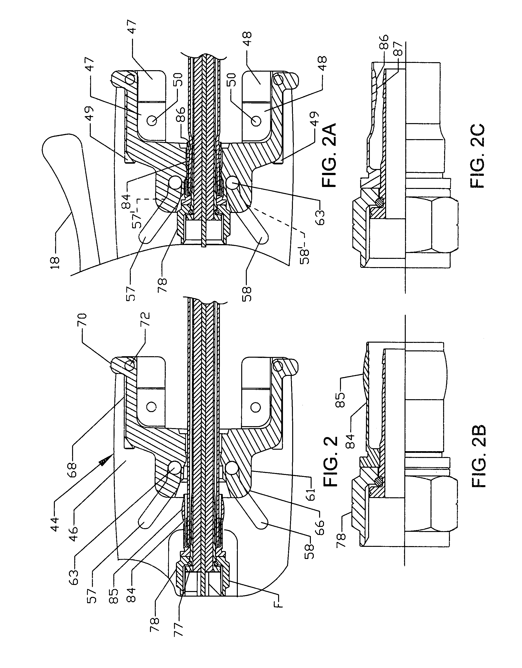
[0041]Referring in more detail to the drawings, one embodiment of hand-held tool 10 is shown in Figures 1A through 6 and is broadly comprised of an elongated body 12 of generally channel-shaped configuration, as best seen from FIGS. 3 and 5. A plunger assembly 15 extends through a plunger-receiving bore 16 in the body, and a lever arm 18 has an offset end portion 19 pivotally mounted in a channel at the rear end of the body 12. A floating link 22 is pivotally attached at 23 in offset relation to the pivot 20 and pivotally attached at its opposite end 24 to an end of a plunger 14. Further, the lever arm 18 is of a width substantially corresponding to the width of the channel in the body 12 so as to be free to pivot from the extreme raised or upright position shown in FIG. 1 to the substantially horizontal position overlying the body 12, as shown in FIG. 4. The plunger assembly 15 comprises a plunger 14 which is slidable through bushing 28 in the bore 16 and terminates in a large holl...


PUM

PropertyMeasurementUnit
lengthsaaaaaaaaaa
diametersaaaaaaaaaa
diameteraaaaaaaaaa

Abstract

A compression tool for connecting a cable fitting to the end of a cable includes a plunger having a chuck at one end together with an extension member releasably connected to the end of the chuck and aligned with enlarged recesses in spaced guideways, dies on the tool can be expanded to permit insertion of the connector fitting and cable into engagement with the end of the chuck or the extension member and contracted to apply a uniform crimping force to the fitting in response to axial force applied to the chuck, and the spaced guideways have angled guide slots to correlate the advancement of the dies with the effective length of the chuck to cause the cable fitting to be contracted into crimping engagement with the end of the cable; and a special cable fitting is provided for smaller cables to compensate for the difference in diameter between standard cables and the smaller cables.

Description

CROSS REFERENCE TO RELATED APPLICATIONS[0001]This application is a continuation-in-part of Ser. No. 10 / 927,884 filed 27 Aug. 2004 for COAXIAL CABLE FITTING AND CRIMPING TOOL by Randall A. Holliday and Robert M. Parker, now U.S. Letters Pat. No. 7,188,507 and incorporated by reference herein.BACKGROUND AND FIELD[0002]The following relates to compression devices, and more particularly relates to a novel and improved hand-held universal compression tool for crimping fittings of different lengths and diameters into sealed engagement with cables, such as, for example, coaxial cables employed in the cable TV industry.[0003]Hand-held compression tools have been devised for crimping a connector onto the end of a coaxial cable and which are characterized in particular by being capable of reducing the diameter of the fitting into a generally circular configuration in response to an axially directed force to the fitting. Representative of these inventions are U.S. Pat. No. 5,392,508 for AXIAL ...

Claims


Application Information

Patent Timeline
Patent Type & Authority Patents(United States)
IPC IPC(8): H01R43/042
CPCB21D39/048H01R9/0518H01R24/44Y10T29/53213Y10T29/53226Y10T29/53209Y10T29/49123H01R2103/00
Inventor HOLLIDAY, RANDALL A.PARKER, ROBERT M.
Owner PPC BROADBAND INC
Why Eureka
Try Eureka