
LED lighting fixture

a technology of led lighting fixtures and led drivers, which is applied in the direction of lighting and heating apparatus, semiconductor devices for light sources, and high-luminance light fixtures using leds as light sources. it can solve the problems of difficult to keep electronic led drivers in water/air tight locations, and difficult to meet the requirements of high-efficiency lighting fixtures. achieve high energy-efficiency and long operating li

Active Publication Date: 2013-06-18
IDEAL IND LIGHTING LLC
View PDF60 Cites 79 Cited by
  • Summary
  • Abstract
  • Description
  • Claims
  • Application Information

AI Technical Summary

Benefits of technology

This solution results in a compact, cost-effective, and reliable LED lighting fixture with improved heat dissipation and protection of electronic components, enabling efficient illumination while reducing the overall size and weight of the fixture.

Problems solved by technology

High-luminance light fixtures using LEDs as the light source present particularly challenging problems.
High cost due to high complexity becomes a particularly difficult problem when high luminance, reliability, and durability are essential to product success.
Keeping electronic LED drivers in a water / air-tight location may also be problematic, particularly when the light fixtures are constantly exposed to the elements.
Dealing with heat dissipation requirements is still another problem area for high-luminance LED light fixtures.
Heat dissipation is difficult in part because high-luminance LED light fixtures typically have many LEDs.
Complex structures for module mounting and heat dissipation have sometimes been deemed necessary, and all of this adds complexity and cost.
Furthermore, previous fixtures utilizing HID lamps and other non-LED light sources typically require a comparatively large lamp compartment with large reflectors for lighting efficiency.
Such fixtures often also require large ballast compartments.
These often result in large overall fixture size and a substantially heavy fixture.

Method used


Image

  • LED lighting fixture
  • LED lighting fixture
  • LED lighting fixture

Examples


Embodiment Construction

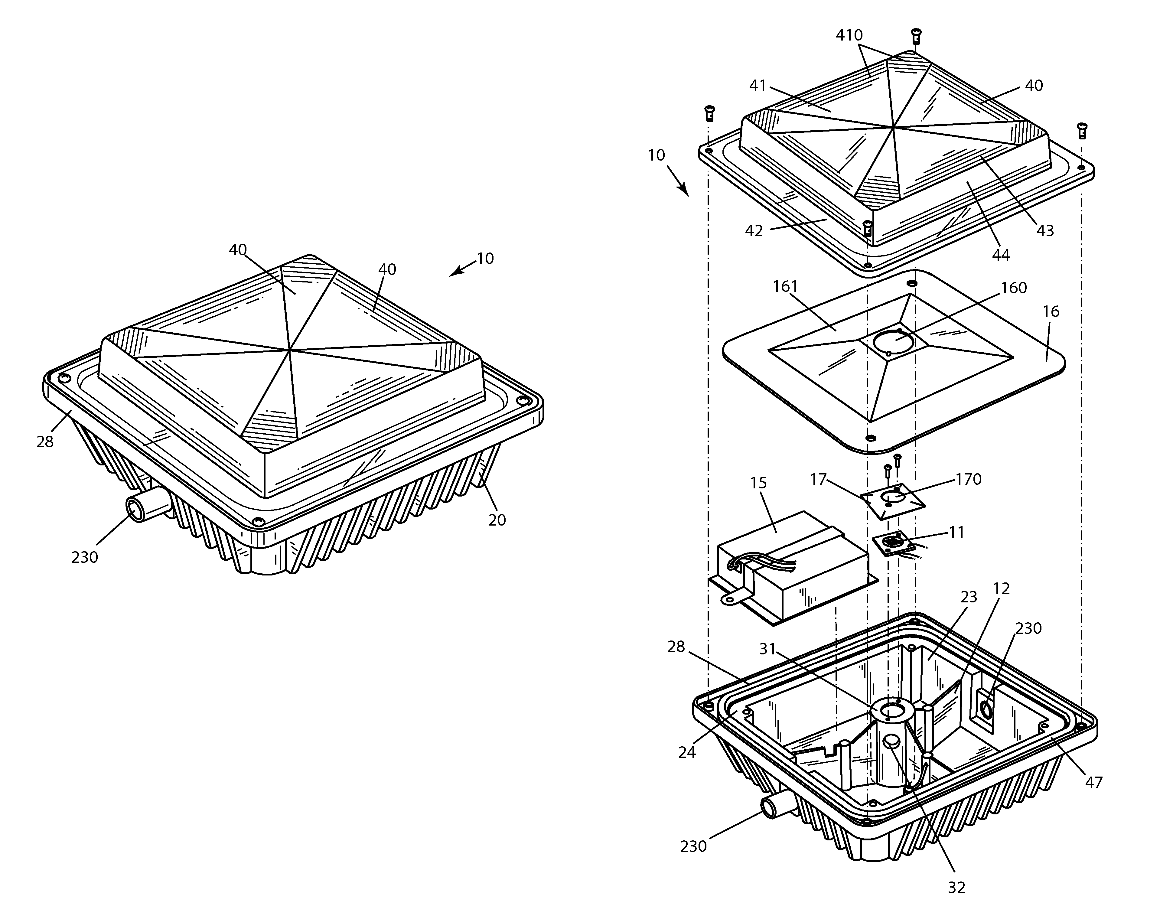
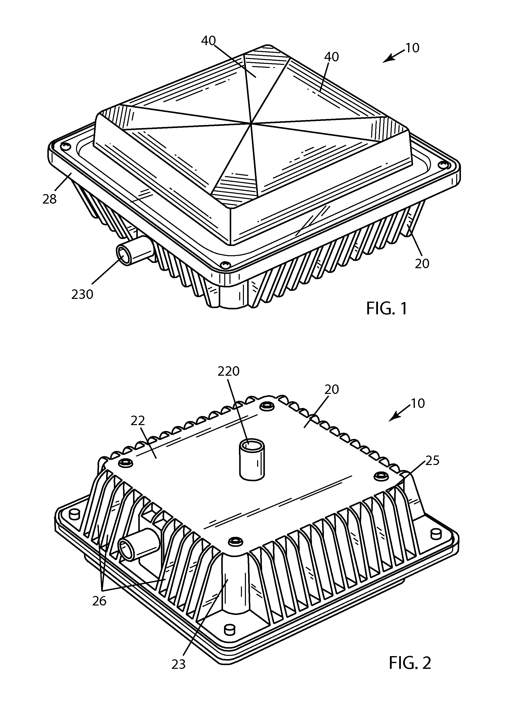
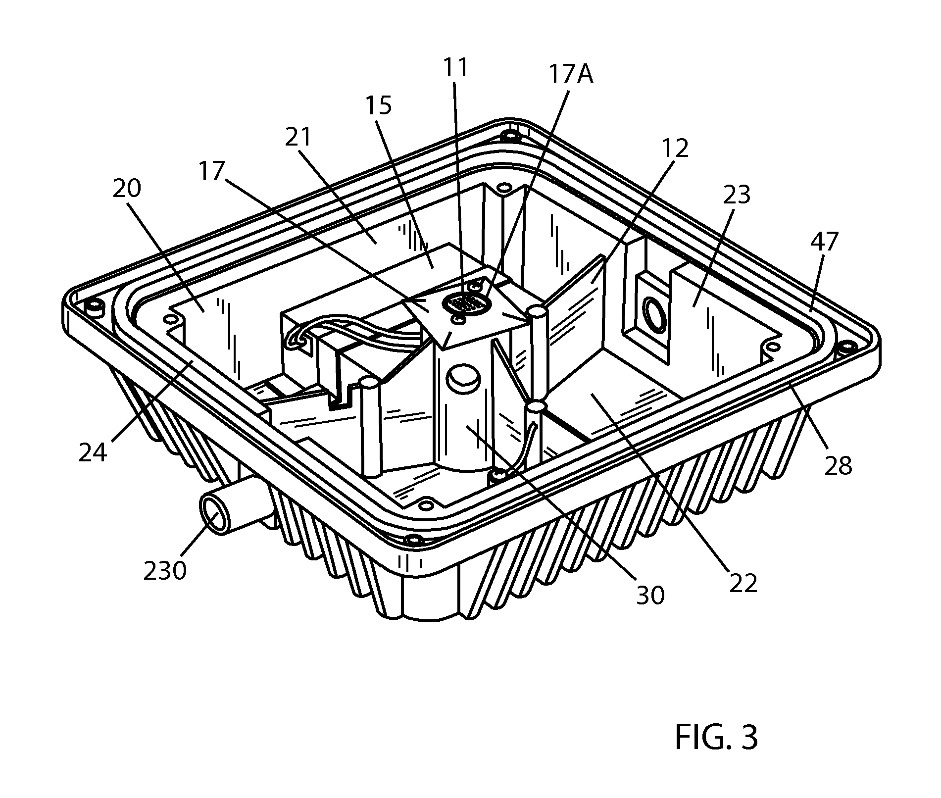
[0040]FIGS. 1-11 illustrate preferred embodiments of an inventive LED lighting fixture 10. As best seen in FIGS. 3, 4, 7, 8 and 11, lighting fixture 10 includes a housing 20 having a hollow interior cavity 21 defined by a backwall 22 and a surrounding wall 23 extending therefrom to a forward edge 24. An LED illuminator 11 is mounted in housing 20. And, an LED-support structure 30 extends in interior cavity 21 from housing 20 to an LED-supporting surface 31 which positions LED illuminator 11 in a desired orientation and is spaced from backwall 22.

[0041]LED-support structure 30 is a heat sink transferring heat from LED illuminator 11 to housing 20. LED-support structure 30 is spaced from surrounding wall 23. LED lighting fixture 10 also includes three interior ribs 12 connecting LED-support structure 30 to surrounding wall 23.

[0042]The outer surface 25 of housing 20 includes a series of fins 26 extending outwardly therefrom. Fins 26 provide further heat dissipation from LED illuminato...


PUM


Abstract

An LED lighting fixture including a housing having a hollow interior cavity defined by a backwall and a surrounding wall extending therefrom to a forward edge. An LED illuminator is mounted in the housing. An LED-support structure extends in the interior cavity from the housing to an LED-supporting surface positioning the LED illuminator in a desired orientation and spaced from the backwall. The LED-support structure is a heat sink transferring heat from the LED illuminator to the housing.

Description

FIELD OF THE INVENTION[0001]This invention relates to light fixtures. More particularly, this invention relates to light fixtures which utilize light-emitting diodes (LEDs) as the light source.BACKGROUND OF THE INVENTION[0002]In recent years, the use of LEDs for various common lighting purposes has increased, and this trend has accelerated as advances have been made in LEDs and in LED-array devices, often referred to as “LED modules.” Indeed, lighting applications which have been served by fixtures using high-intensity discharge (HID) lamps and other light sources are now increasingly beginning to be served by LED fixtures. Creative work continues in the field of using LEDs for light fixtures in various applications.[0003]High-luminance light fixtures using LEDs as the light source present particularly challenging problems. High cost due to high complexity becomes a particularly difficult problem when high luminance, reliability, and durability are essential to product success. Keep...

Claims


Application Information

Patent Timeline
Patent Type & Authority Patents(United States)
IPC IPC(8): F21V29/00
CPCF21V19/0055F21V23/009F21V29/773F21V5/00F21V29/002F21K9/30F21V29/70F21V29/763F21V21/30F21V31/005F21Y2101/02F21Y2105/001F21V27/02F21V23/002F21K9/20F21Y2105/10F21Y2115/10
Inventor WILCOX, KURT S.GUILLIEN, WAYNETSAO, FRANK
Owner IDEAL IND LIGHTING LLC
Learn More