Laminated core

a technology of laminated core and core plate, which is applied in the direction of dynamo-electric components, magnetic circuit stationary parts, magnetic circuit shape/form/construction, etc., can solve the problems of motor core deformation, achieve the effect of preventing extreme stress concentration, ensuring the life of cutting tools, and avoiding press and shear

Inactive Publication Date: 2013-06-18
MITSUI HIGH TEC INC
View PDF19 Cites 8 Cited by
  • Summary
  • Abstract
  • Description
  • Claims
  • Application Information

AI Technical Summary

Benefits of technology

[0020]The laminated core according to the present invention has the following effects.
[0021](1) The first aspect of the present invention provides the laminated core (bending core) formed with the predetermined number of the straight connected core segments, each of the straight connected core segments having the segment yokes connected together by the bendable connecting portions, each of the segment yokes having the magnetic pole piece, the straight connected core segments laminated and bent at the connecting portions in a ring shape. The second aspect of the present invention provides the laminated core (winding core) formed with the strip of the connected core segment, the strip of the connected core segment having the segment yokes connected together by the bendable connecting portions, each of the segment yokes having one or more of the magnetic pole pieces, the strip of the connected core segment bent at the connecting portions and wound. In the laminated cores according to the first and second aspects of the present invention, since the slit is formed via the second through-hole having the circular arc, the stress (tension) generated by bending the connecting portion is absorbed by the second through-hole, and extreme stress concentration is prevented. Thus, cracks and fractures are hardly generated around the connecting portion, ensuring the quality of the product, i.e., the laminated core.
[0022](2) In the laminated cores according to the first and second aspects of the present invention, the radially inward section of the connecting portion includes the V-shaped cutout formed via the first through-hole having the circular arc, whereas the radially outward section of the connecting portion includes the slit formed via the second through-hole having the circular arc. Thus, it is easy to press and shear the V-shaped cutout and the slit, and the life of the cutting tool is ensured.
[0023](3) In the laminated cores according to the first and second aspects of the present invention, if the connecting portion extending in the circumferential direction has a uniform or substantially uniform width in a longitudinal direction, the stress generated by bending the connecting portion is distributed, and thus the deformation of the connecting portion (e.g., a bulge in the thickness direction) due to the concentrated bending stress on one side of the connecting portion can be minimized.
[0024](4) If the radially outward end of the connecting portion is located inward from the outermost end of the laminated core by the distance of 3% of more of the radius R, a gap between the blanked adjacent segment yoke pieces becomes smaller than that in the conventional laminated core. Thus, the material yield of the iron core piece can be improved.
[0025](5) The bottom of the V-shaped cutout is located outward from a radially inward end of the segment yoke piece by the distance of more than 40% of the radial width of the segment yoke piece. With this structure, a contact area of the adjacent segment yoke pieces can be secured, preventing a deterioration of magnetic characteristics of the laminated core.

Problems solved by technology

The projected connecting portions interfere with a housing to decrease retention of the motor core or to cause a deformation of the motor core.

Method used


Image

  • Laminated core
  • Laminated core
  • Laminated core

Examples


first embodiment

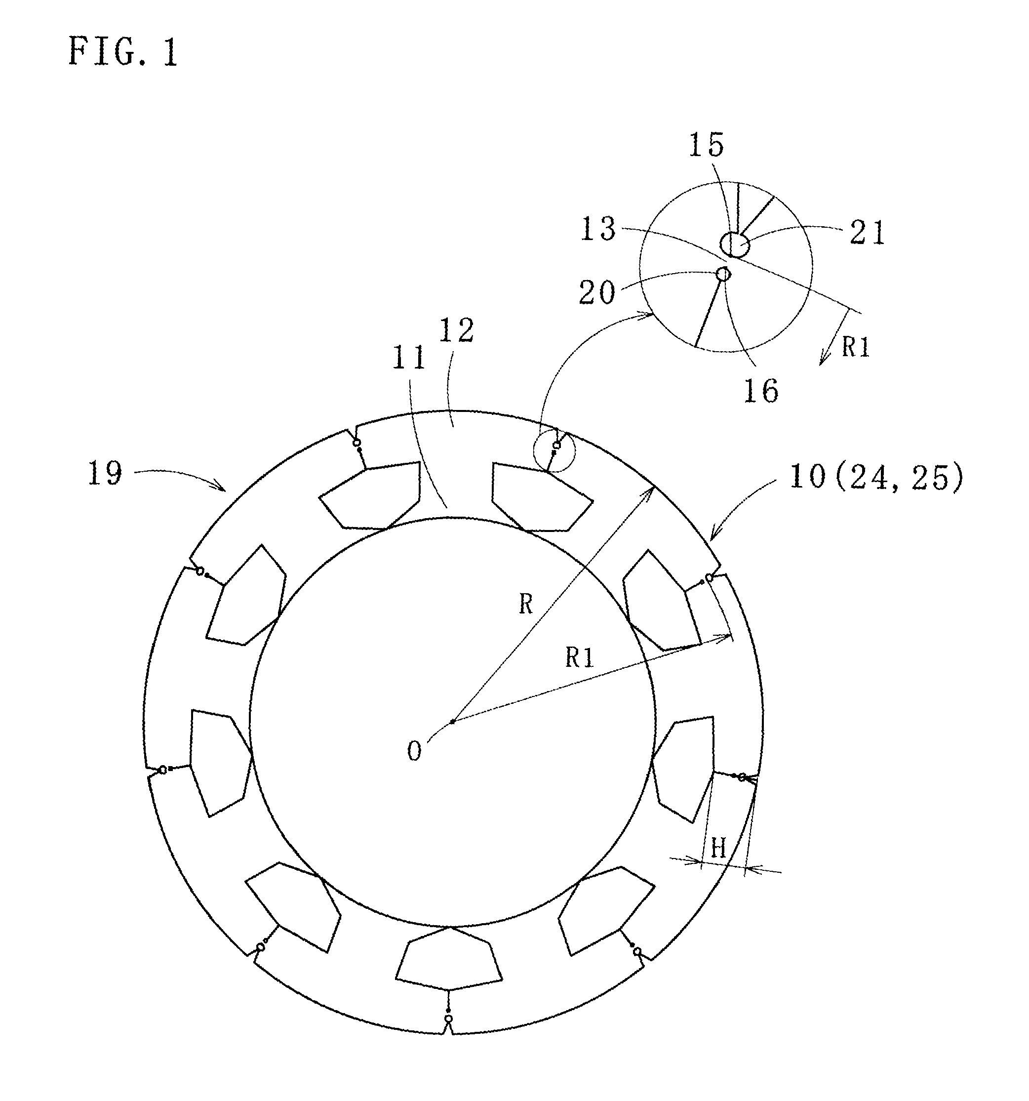
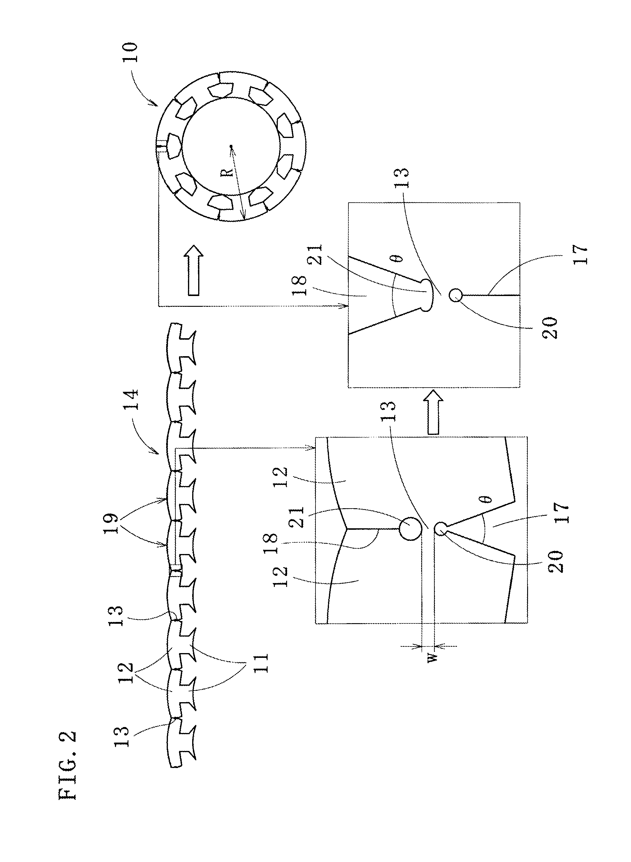
[0040]FIG. 1 shows a laminated core 10 according to the present invention. The laminated core 10 is a stator core for a motor. As shown in FIG. 2, a plurality of segment yokes 12 each having a magnetic pole piece 11 are linked together by bendable connecting portions 13, thereby forming a straight connected core segment 14. A predetermined number of the connected core segments 14 are laminated and bent at the connecting portions 13, thereby forming the laminated core 10.

[0041]As shown in FIGS. 1 and 2, a radially outward end 15 of the connecting portion 13 is located inward from an outer periphery of the segment yoke 12 by a distance of 3% or more (preferably 5% or more, further preferably 10% or more) of a radius R of the laminated core 10. A radially inward end 16 of the connecting portion 13 is located outward from an inner end of the segment yoke 12 by a distance of more than 40% (preferably 50% or more) of a width H of the segment yoke 12. It is preferable that a width w of the...

second embodiment

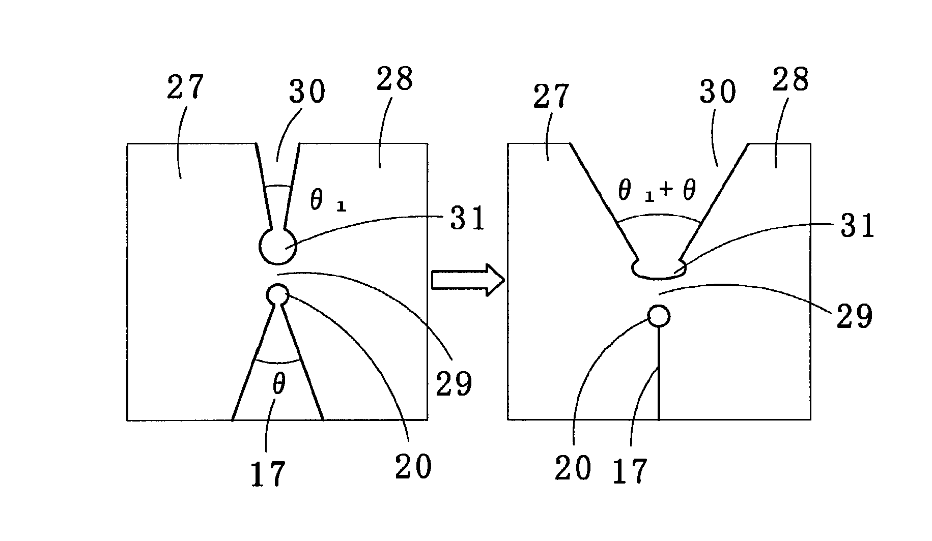
[0055]In the laminated core 24 according to the present invention, adjacent segment yokes 27 and 28 of a connected core segment in use are connected by a connecting portion 29, and instead of the above-described slit, a V-shaped cutout 30 is formed in a radially outward section of the connecting portion 29. Here, if an opening angle of the V-shaped cutout 30 is θ1 (e.g., 5 to 30 degrees) and the opening angle of the V-shaped cutout 17 formed inward from the connecting portion 29 is θ, the opening angle of the V-shaped cutout 30 in the laminated core 24 is (θ1+θ).

[0056]Based on the above conditions, a circular hole 31 (one example of the second through-hole) is formed, and then the slit (the V-shaped cutout 30) is formed such that the circular hole 31 is placed at a bottom (radially inward section) of the V-shaped cutout. This structure makes the presswork easy and prolongs the life of the cutting tool.

[0057]The laminated core 25 according to the third embodiment of the present inven...

fourth embodiment

[0059]In a laminated core according to the present invention in FIG. 7, a radially inward section of a connecting portion 48 includes a V-shaped cutout 49, and a radially outward end of the V-shaped cutout 49 includes a first through-hole 50 made of a circular hole. Further, a radially outward section of the connecting portion 48 includes a second through-hole 51 made of a curved hole, and a radially outward section of the second through-hole 51 includes a slit 52.

[0060]Radial ends of the second through-hole 51 are formed by an outer circle 53 and an inner circle 54. Curvature radii r1, r2, and r3 of the outer circle 53, the inner circle 54, and the first through-hole 50 have a center at the same position as a center of the first through-hole 50, therefore the connecting portion 48 has a uniform width in a circumferential direction. For this reason, if the connecting portion 48 is bent (curved), a bending stress is equally applied in the circumferential direction of the connecting p...


PUM

PropertyMeasurementUnit
opening angleaaaaaaaaaa
widthaaaaaaaaaa

Abstract

A laminated core 10 improves material yield and prevents cracks or breakages of core pieces by relaxing stress on connecting portions 13. A connected core segment 14 to be the laminated core 10 includes: a V-shaped cutout 17 located radially inward from the connecting portion 13, the cutout 17 opening in a radially inward direction with an opening angle of 360° / n given that n is a number of core segments 19; a slit 18 located radially outward from the connecting portion 13, the slit 18 dividing adjacent segment yokes 12 located radially outward from the connecting portion; a first through-hole 20 having a circular arc formed in a radially outward end of the cutout 17 in contact with the connecting portion 13; and a second through-hole 21 having a circular arc formed in a radially inward end of the slit 18 in contact with the connecting portion 13.

Description

TECHNICAL FIELD[0001]The present invention relates to a laminated core, and more particularly to a so-called “bending core” and a so-called “winding core.” In manufacture of the bending core, a straight laminated core is formed by laminating a predetermined number of the connected core segments, each of which includes segment yokes connected together by bendable connecting portions, and the straight laminated core is bent at the connecting portions in a ring shape. In manufacture of the winding core, a connected core segment, including segment yokes connected together by bendable connecting portions, is bent at the connecting portions and wound. In both of the cores, each of the segment yokes includes one magnetic pole piece, forming a yoke of the connected core segment. In this regard, the bending core is also referred to as “Poki-poki core” in Japanese (“Poki-poki” is a Japanese registered trademark), since each connecting portion is bent with a cracking sound of poki-poki when th...

Claims


Application Information

Patent Timeline
Patent Type & Authority Patents(United States)
IPC IPC(8): H02K1/06
CPCH02K1/148H02K1/16H02K15/026B21D28/10B21D28/22H02K2213/03
Inventor MAKI, KIYOHISAHASUO, YUSUKEARAZOE, MEI
Owner MITSUI HIGH TEC INC
Why Eureka
Try Eureka