Discharge lamp and discharge lamp device

a discharge lamp and discharge lamp technology, applied in the direction of electric discharge lamps, gas-filled discharge tubes, solid cathodes, etc., can solve the problems of low illumination intensity and detrimental to practical implementation, and achieve the effect of maintaining power supply and good efficiency

Inactive Publication Date: 2013-06-18
NAT UNIV CORP SHIZUOKA UNIV
View PDF6 Cites 0 Cited by
  • Summary
  • Abstract
  • Description
  • Claims
  • Application Information

AI Technical Summary

Benefits of technology

[0013]According to the present invention a point light source can be achieved while maintaining power supply with good efficiency.

Problems solved by technology

Microwave electrodeless lamps configured in such a manner are illuminated by microwaves picked up by the coils, however they have low illumination intensity which is detrimental to practical implementation.

Method used


Image

  • Discharge lamp and discharge lamp device
  • Discharge lamp and discharge lamp device
  • Discharge lamp and discharge lamp device

Examples


Embodiment Construction

[0018]Detailed explanation follows regarding an exemplary embodiment of the present invention, with reference to the drawings. In the following an exemplary embodiment is explained of a discharge lamp device that employs a high voltage high-intensity discharge (HID) lamp as the discharge lamp.

[0019]Discharge Lamp Device Configuration

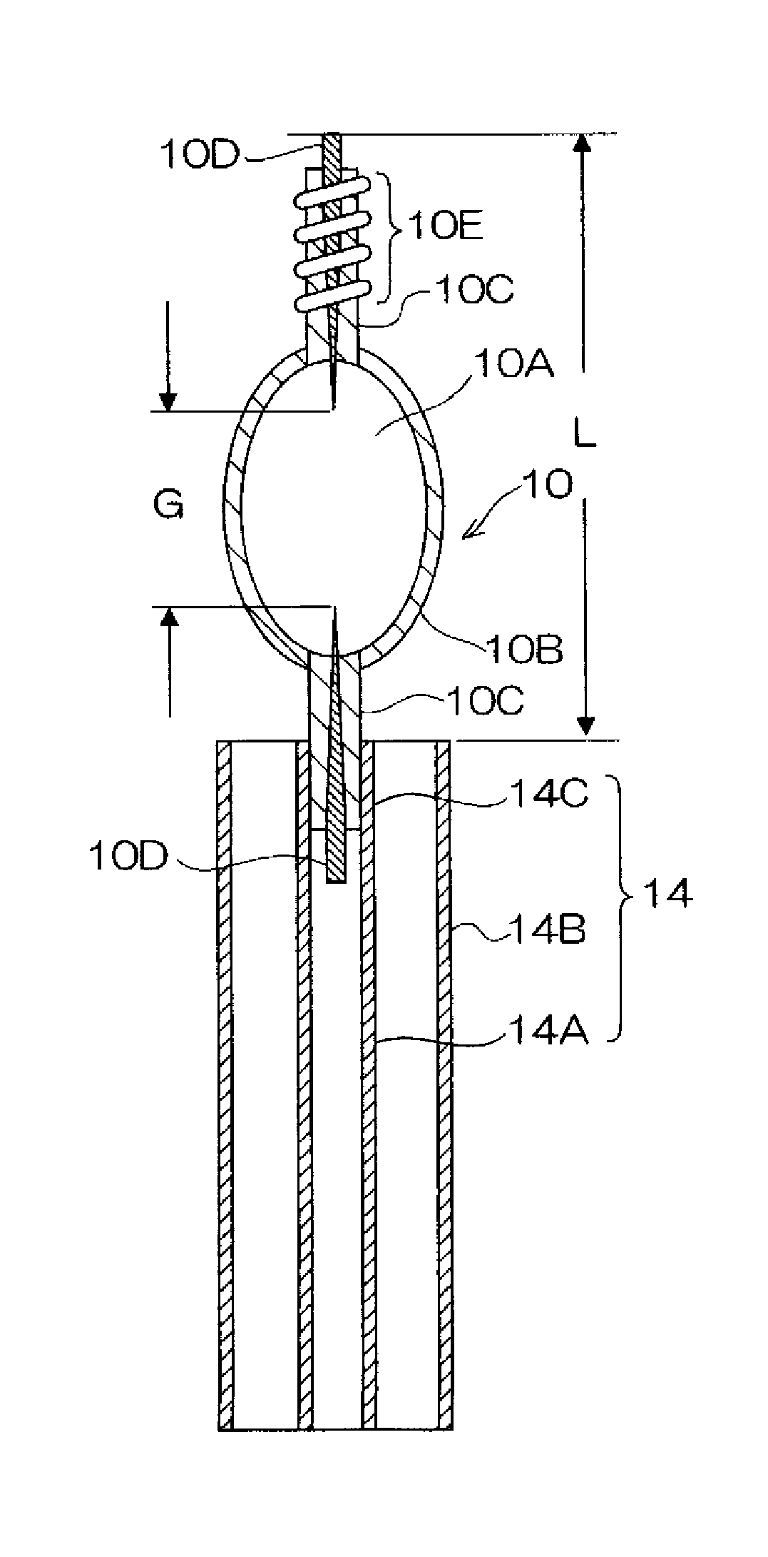
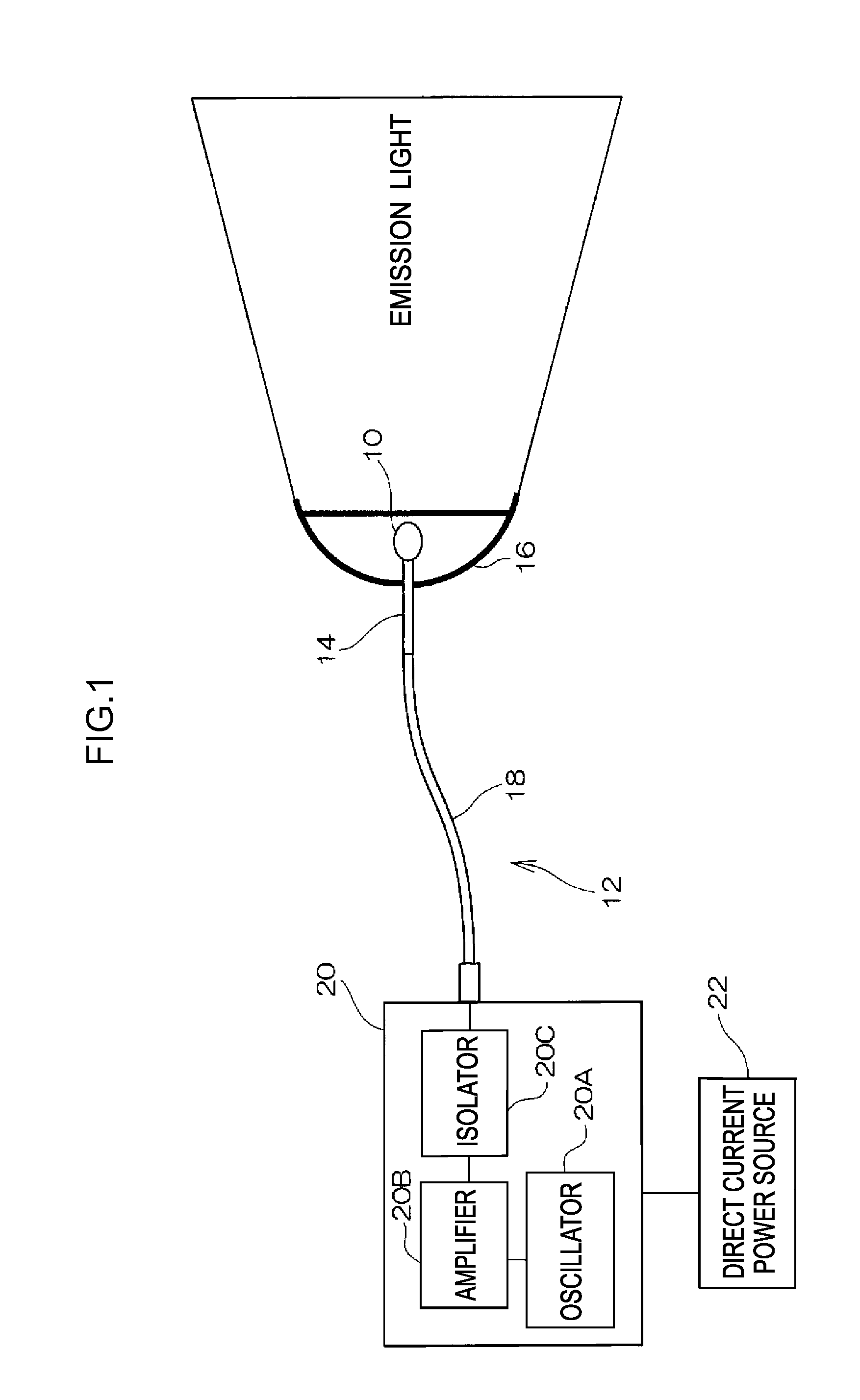
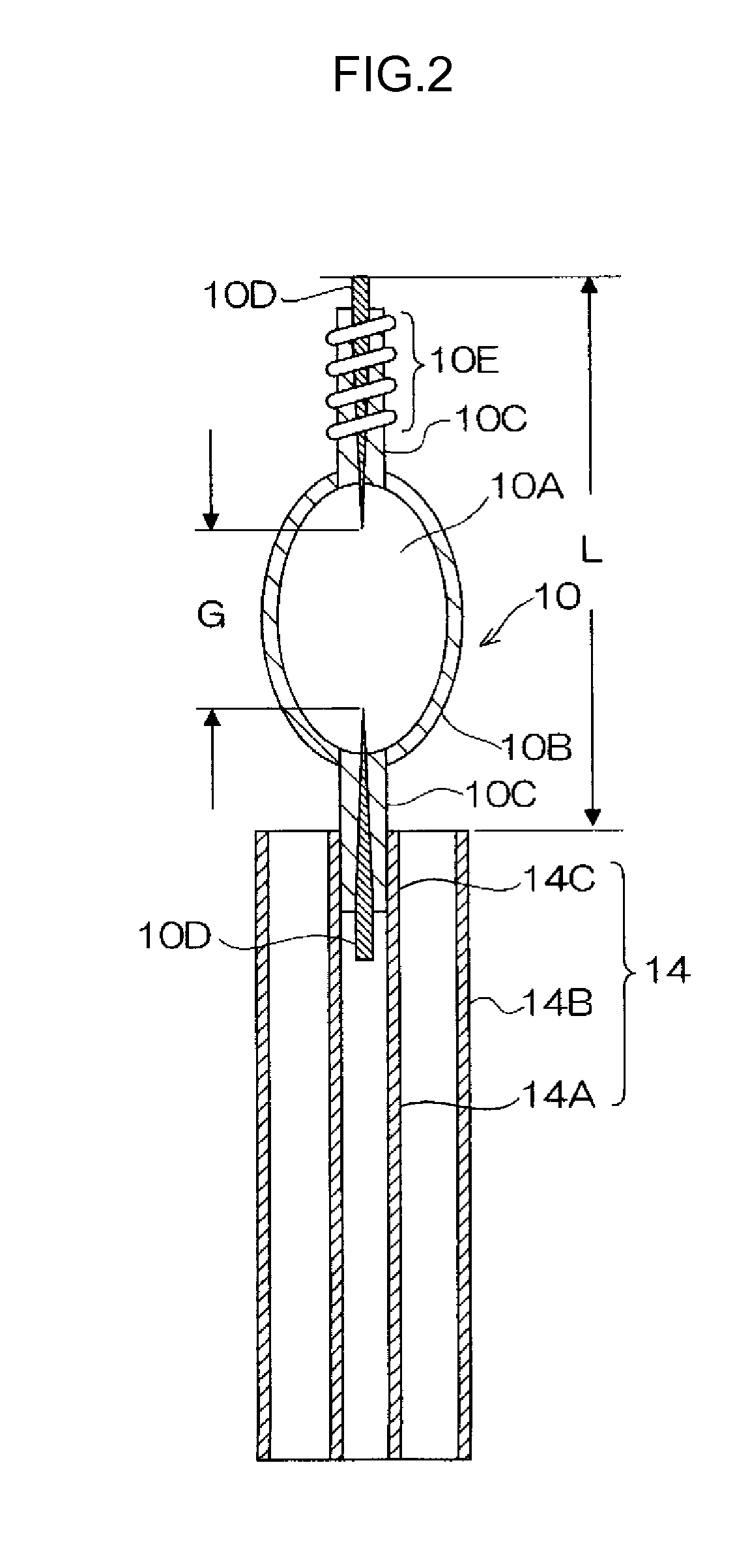
[0020]FIG. 1 is a diagram illustrating a configuration of a discharge lamp device according to an exemplary embodiment of the present invention. The discharge lamp device includes an HID lamp 10 that is a high-intensity discharge lamp, and a discharge lamp illumination device 12 for illuminating the HID lamp 10.

[0021]A launcher 14 is provided in the discharge lamp illumination device 12 to act as a wave guide for electromagnetic waves such as radiowaves (RF) or microwaves. A light collecting reflecting mirror 16 is fixed to one end of the launcher 14 such that the light emission section of the HID lamp 10 is positioned at the focal point of the light col...


PUM


Abstract

A discharge lamp including: a discharge vessel 10B configured by a light-transmissive non-electrically conducting member with a light-emitting substance sealed inside; one out of a pair of antenna members 10D with a portion at one end provided inside the discharge vessel 10B and a portion at the other end projecting outside the discharge vessel 10B and covered by a non-electrically conducting member; the other of the pair of antenna members 10D with a portion at one end provided inside the discharge vessel 10B and a portion at the other end projecting outside the discharge vessel 10B, covered by a non-electrically conducting member and capable of being connected to an electromagnetic waveguide path; and a loading coil 10E wound around the portion of the first antenna member 10D that is covered by the non-conducting member. A point light source can be achieved as well as performing power supply with good efficiency.

Description

TECHNICAL FIELD[0001]The present invention relates to a discharge lamp and a discharge lamp device.BACKGROUND ART[0002]Compact high-intensity discharge lamps (HID lamps) are widely used as light sources employed in vehicle headlights and projectors.[0003]There are descriptions of microwave electrodeless lamps in Japanese Patent Application Laid-Open (JP-A) Nos. 2008-140575 and 2008-140576, configured with a transparent vessel including an inflation section with a sealed space in which a light-emissive substance is sealed and a pair of capillaries connected to face the inflation section; internal conductors sealed into each of the capillaries; and coils acting as external conductors wound at the outer periphery of the capillaries over substantially the length direction range of the internal conductors. Microwave electrodeless lamps configured in such a manner are illuminated by microwaves picked up by the coils, however they have low illumination intensity which is detrimental to pra...

Claims


Application Information

Patent Timeline
Patent Type & Authority Patents(United States)
IPC IPC(8): H05B41/24H01Q1/26
CPCH01J61/86H01J65/044H01J65/048
Inventor KANDO, MASASHI
Owner NAT UNIV CORP SHIZUOKA UNIV
Why Eureka
Try Eureka